On-line thermal imaging temperature monitoring method for power transformation device

A technology of substation equipment and thermal imaging, applied in the direction of electric radiation detectors, televisions, electrical components, etc., can solve the problems of limited operator installation height, single operation experience, and inability to fully observe most parts of the equipment

Inactive Publication Date: 2014-09-17
福建闽能长裕智能科技有限公司
View PDF8 Cites 12 Cited by
  • Summary
  • Abstract
  • Description
  • Claims
  • Application Information

AI Technical Summary

Problems solved by technology

[0004] 1. Due to the lack of an effective supervision mechanism, the equipment inspection rate and high work quality cannot be guaranteed
[0005] 2. Operation experience is a kind of technical ability to ensure the safe operation of power equipment, but the accumulation process of operation experience is unique
[0006] 3. Manually use portable infrared equipment to detect the working thermal state of the live equipment, which is limited by the height of the operator and the installation height of the equipment, and most positions of the equipment cannot be fully observed
[0007] 4. For thermal state monitoring of operating equipment in unattended substations, if it is a portable infrared device, it will often cause defects such as increased labor intensity and untimely diagnosis

Method used


Image

  • On-line thermal imaging temperature monitoring method for power transformation device
  • On-line thermal imaging temperature monitoring method for power transformation device
  • On-line thermal imaging temperature monitoring method for power transformation device

Examples


Embodiment Construction

[0034] In order to further explain the technical solutions of the present invention, specific examples are given below to illustrate in detail.

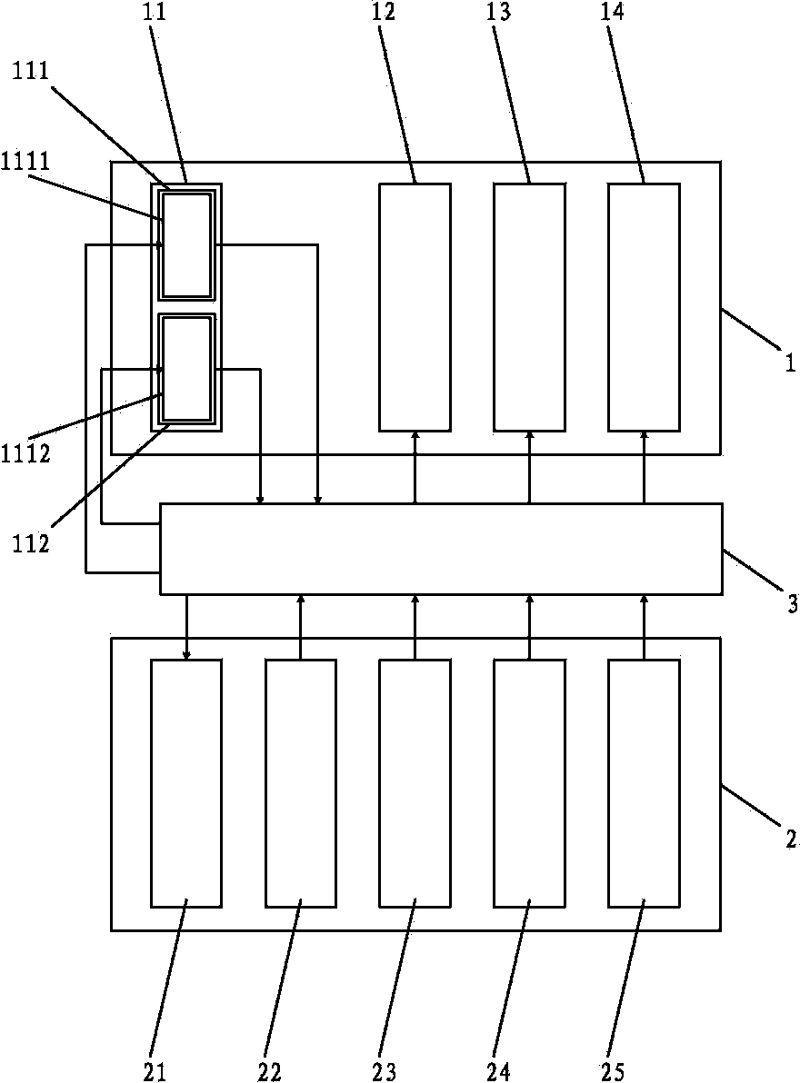
[0035] A method for on-line monitoring of thermal imaging temperature of substation equipment of the present invention, such as Figure 1-4 As shown, the end where the substation equipment is located is the field end 1, and the end where the monitoring customer is located is the client end 2.

[0036]The present invention adopts a plurality of video signal collection devices 11 to carry out video signal collection to a plurality of field end monitoring points; Video signal collection device 11 comprises visible light video signal collection device 111 and infrared video signal collection device 112; Visible light video signal collection device 111 and infrared The video signal acquisition device 112 respectively collects the visible light video signal and the infrared video signal of the corresponding monitoring point, and transmits ...


PUM


Abstract

The invention provides an on-line thermal imaging temperature monitoring method for a power transformation device. A plurality of video signal collecting devices are used for collecting video signals of a plurality of field end monitoring points. A monitoring server transmits a visible light video signal to a client side monitor, visible light video windows of the monitoring points are displayed on the client side monitor, the monitoring server identifies the temperature of the field of the power transformation device according to the infrared thermal imaging hue of infrared video signals, and when the temperature exceeds the set range, the monitoring sensor transmits the infrared video signals to the client side monitor. The infrared video signals jump out to be distributed on a screen of the whole client side monitor in the form of the infrared thermal imaging windows with the visible light video window at the corresponding monitoring point, a specific device, a temperature value window and an electronic map window. Thus, the on-line thermal imaging temperature monitoring method is higher in caution and indication performance, the situations of points to be monitored, the temperature and the position of the points and the like can be clearer, the temperature can be monitored online conveniently and pertinently, and the practicality is high.

Description

technical field [0001] The invention relates to the field of temperature monitoring methods for power transformation equipment, in particular to an online monitoring method for thermal imaging temperature of power transformation equipment. Background technique [0002] The operating status of power equipment directly determines the safety and efficiency of the power system. There are a large number of equipment such as transformers, busbars, disconnectors, circuit breakers, coupling capacitors, and high-voltage cables in substations. No matter what kind of equipment is in an abnormal working state, if it is not dealt with in time, it may develop into a failure, and even cause equipment damage or personal accident, which will cause immeasurable consequences. Because infrared detection technology can obtain equipment operating status information in a long-distance, non-contact, real-time, and fast online monitoring method, it has the advantages of high resolution, intuitive im...

Claims


Application Information

Patent Timeline
Patent Type & Authority Applications(China)
IPC IPC(8): G01J5/10H04N5/33
Inventor 张少春傅承委傅建阳
Owner 福建闽能长裕智能科技有限公司
Why Eureka
Try Eureka