
Aiming controller and inertial unit prism initial azimuth automatic calculating method thereof

A technology of aiming controller and inertial group prism, which is applied in the direction of control using feedback, can solve the problems of poor accuracy, low efficiency, manual labor, etc., and achieve the effect of reducing work difficulty and improving efficiency.

Active Publication Date: 2014-09-17
BEIJING INST OF SPACE LAUNCH TECH +1
View PDF3 Cites 0 Cited by
  • Summary
  • Abstract
  • Description
  • Claims
  • Application Information

AI Technical Summary

Problems solved by technology

[0004] In order to solve the above problems, the present invention provides an aiming controller, which solves the problem of low efficiency and poor accuracy caused by manual methods for the calculation of the initial azimuth angle of the inertial group prism and the transmission of aiming data in the existing aiming equipment

Method used


Image

  • Aiming controller and inertial unit prism initial azimuth automatic calculating method thereof
  • Aiming controller and inertial unit prism initial azimuth automatic calculating method thereof
  • Aiming controller and inertial unit prism initial azimuth automatic calculating method thereof

Examples


Embodiment Construction

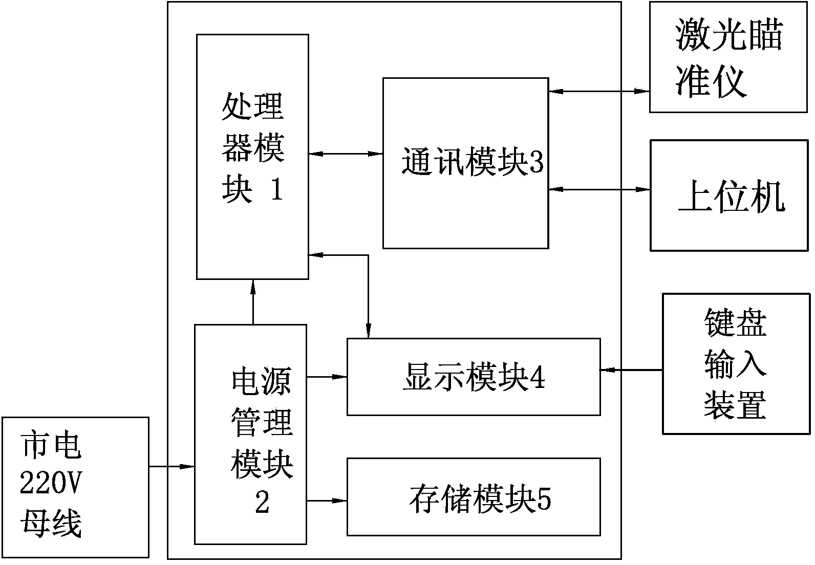
[0057] Attached below figure 1 The present invention is described in detail:

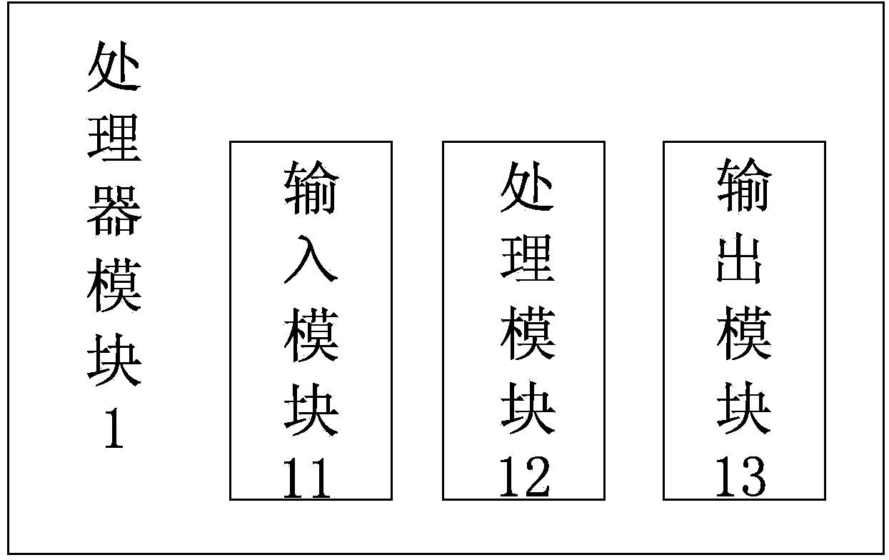
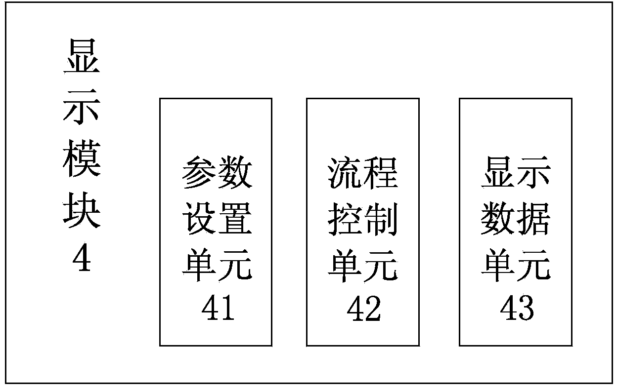
[0058] An aiming controller in this embodiment includes a processor module 1, a communication module 3, a power management module 2, a display module 4, and a storage module 5;

[0059] The communication module 3 , the power management module 2 , the display module 4 and the storage module 5 are respectively connected to corresponding pins of the processor chip in the processor module 1 .

[0060] The input terminal of the power management module 2 is connected to the 220V mains power bus, and the output terminal is connected to the processor module 1 , the display module 4 and the storage module 5 respectively.

[0061] The input terminal of the display device 4 is connected with the keyboard input device.

[0062] The processor module 1 is respectively connected with the laser collimator and the host computer through the communication module 3 .

[0063] combine figure 2 As shown, the process...


PUM


Abstract

The invention discloses an aiming controller. The aiming controller comprises a processor module, a communication module, a power management module, a display module and a storage module. The processor module is a CPU controller. The CPU controller is used for reading the data of a laser collimator which is connected with the CPU controller, displaying the data through the display module, and meanwhile storing the data through the storage module. A CPU processor obtains the data of marker post aiming operation and inertial unit aiming operation through the laser collimator, the initial azimuth of an inertial unit prism can be calculated automatically through a formula, data are displayed through the display module, and the data are further uploaded to an upper computer through the communication module. The invention further provides an inertial unit prism initial azimuth automatic calculating method of the aiming controller. Aiming data can be transmitted and stored, the initial azimuth of the prism can be calculated automatically, one-button prism initial azimuth automatic calculating can be achieved, working difficulty is lowered, and efficiency is improved.

Description

technical field [0001] The invention relates to an aiming device and a data processing method thereof, in particular to an aiming device and a method for automatically calculating the initial azimuth angle of an inertial group prism. Background technique [0002] In the process of photoelectric autocollimation and aiming, aiming equipment needs to perform operations such as aiming at the benchmark, aiming at the inertial group, calculating the initial azimuth angle of the inertial group prism, and transmitting aiming data. The calculation of the initial azimuth angle of the inertial group prism of the existing aiming equipment and the transmission of aiming data are all manual, which affects the aiming efficiency, and the correctness of the manual calculation is difficult to guarantee, thus reducing the working accuracy of the aiming equipment. [0003] At present, there is no technology in China to automatically calculate the initial azimuth angle of the inertial group pris...

Claims


Application Information

Patent Timeline
IPC IPC(8): G05D3/12
Inventor 狄世超高明杰董彦维宋小艳范毅
Owner BEIJING INST OF SPACE LAUNCH TECH
Learn More