
Air expansion shaft transferring mechanism, air expansion shaft circulating mechanism and full-automatic winding machine

A transfer mechanism and inflatable shaft technology, applied in the direction of coiling strips, thin material handling, transportation and packaging, etc., can solve the problems of low work efficiency, high safety hazards, easy to be interrupted, etc., to improve production efficiency, reduce The effect of labor costs

Pending Publication Date: 2019-05-21
湖南工业智能体创新研究院有限公司
View PDF8 Cites 0 Cited by
  • Summary
  • Abstract
  • Description
  • Claims
  • Application Information

AI Technical Summary

Problems solved by technology

Manual operation has the problems of low degree of automation, low work efficiency, and high safety hazards; and because the speed of cloth roll winding and forming is fast, and the speed of manual extraction and placement of the air shaft is slow, the process of cloth roll winding is easily interrupted, and the required turnover The number of air shafts is more

Method used


Image

  • Air expansion shaft transferring mechanism, air expansion shaft circulating mechanism and full-automatic winding machine
  • Air expansion shaft transferring mechanism, air expansion shaft circulating mechanism and full-automatic winding machine
  • Air expansion shaft transferring mechanism, air expansion shaft circulating mechanism and full-automatic winding machine

Examples


Embodiment

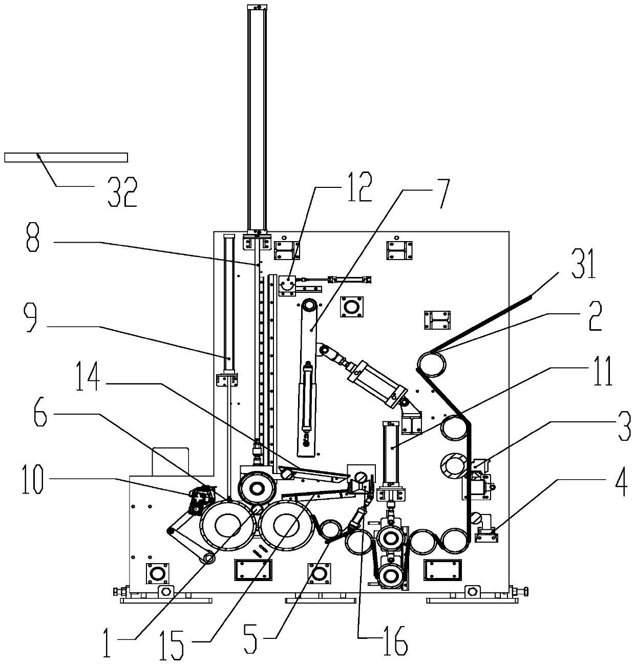
[0032] Reference figure 1 , the fully automatic winding machine in the present embodiment comprises cloth guide roller 2, cloth cutting device 3, distribution roll device 4, spoke expanding device 5, cloth pressing roll device 8, cloth supporting roller device 6, cloth roll device 7 And the side wall (not labeled in the figure), also includes the air shaft transmission mechanism, the air shaft transmission mechanism is used to transfer the air shaft 1 to the carrier roller device 6. The main structures and functions of each device are introduced respectively below, and in order to avoid redundant description, only a brief introduction is made to the prior art known in the technical field.

[0033] Cloth guide roller 2: Allow the cloth roll 31 to be diverted from the external equipment to the cutter roller through the cloth guide roller 2, so as to prepare for the next step of automatic pressing and slitting.

[0034] Cloth cutting device 3: The pneumatic cutter presses the pn...


PUM


Abstract

The invention discloses an air expansion shaft transferring mechanism which is arranged in a winding machine and used for transferring air expansion shafts. The air expansion shaft transferring mechanism comprises an air expansion shaft receiving device, a shaft taking device, a sliding chute device and an air expansion shaft turning device; the air expansion shaft receiving device comprises two clamping arms arranged at a certain distance and used for receiving and temporarily storing the air expansion shafts; the shaft taking device comprises a driving belt and a clamping base connected withthe driving belt; the sliding chute device comprises a first sliding chute arranged between the shaft taking device and the air expansion shaft turning device; and the air expansion shaft turning device comprises a turning chute and a second power unit, and the second power unit is arranged on the bottom side of the turning chute and used for driving the turning chute to incline. The invention further provides a full-automatic winding machine. The full-automatic winding machine comprises the air expansion shaft transferring mechanism, cloth guiding rolls, a cloth cutting device, a cloth rolldividing device, an expanding device, a cloth carrier roll device and a cloth roll kicking device. The winding machine can automatically receive the air expansion shafts and transfer the air expansionshafts according to the process rhythm, and then automatic transferring and recycling of the air expansion shafts are achieved; and compared with a traditional winding machine, the production efficiency is greatly improved, and the labor cost is reduced.

Description

technical field [0001] The invention belongs to the technical field of winders, in particular, the invention relates to an air shaft transmission mechanism, an air shaft circulation mechanism and a fully automatic winder. Background technique [0002] After the textile fabric is produced and processed, a winding mechanism is used to store and organize the textile fabric, so as to facilitate the storage, transportation and sales of the textile fabric. Commonly used winding devices for textile cloth in the prior art all wind the cloth roll on the inflatable shaft, cut the cloth roll after completing one winding, and then send the formed cloth roll out of the winding device. Therefore, before each winding cloth roll starts, a new air expansion shaft is required to be in place in time. And the present technique is to adopt artificially to extract the air expansion shaft from the cloth roll that has been formed and sent out, and then be placed into the winding device. Manual op...

Claims


Application Information

Patent Timeline
Patent Type & Authority Applications(China)
IPC IPC(8): B65H19/30B65H19/26
Inventor 朱栗波张海海高金锐徐岩朱垂桥胡俊文李煊红孟磊何伟
Owner 湖南工业智能体创新研究院有限公司
Learn More