

Vibration power generator
A technology of vibrating generators and movable rods, which is applied in the directions of motors, electric vehicles, electrical components, etc., can solve the problems of complex structure and large volume of vibration generators, and achieve the effect of compact structure and small volume.
- Summary
- Abstract
- Description
- Claims
- Application Information
AI Technical Summary
Problems solved by technology
Method used
Image

Examples
specific Embodiment 1
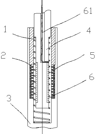
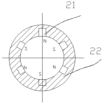
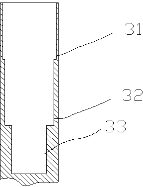
[0022] Please refer to figure 1 , figure 2 , image 3 , a vibration generator, a hollow cavity 33 of the shell 3 has a stepped hole 32, and a magnet component 2 is placed in the stepped hole; the upper end of the magnet component 2 has a sleeve 1, and the sleeve 1 is placed in the hollow cavity of the shell 3 33 in the upper end step hole 31; the movable member is made of a movable rod 4 and a spring 5, one end of the spring 5 is placed on the shoulder 42 of the movable rod, and the other end is placed at the bottom of the hollow cavity 33 of the shell 3, and the outer diameter of the spring 5 is Slightly smaller than the inner diameter of the housing hollow cavity 33; the coil 6 is fixed in the groove 44 on the movable rod 4, and the movable rod 4 is provided with a lead hole 43 inside, and the electrode lead 61 of the coil 6 passes through the lead hole 43 and the battery (not shown in the figure) out) electrical connection.
[0023] The magnet member 2 is composed of se...
specific Embodiment 2
[0026] Please refer to figure 2 , image 3 , Figure 4 , a vibrating generator, a hollow cavity 33 of the casing 3 has a stepped hole 32, and the coil 6 and the iron core 7 are placed in the stepped hole, wherein the coil 6 is located inside the iron core 7; the upper ends of the coil 6 and the iron core 7 There is a sleeve 1 at the bottom, the sleeve 1 is placed in the upper step hole 31 of the hollow cavity 33 of the shell 3; the shell 3 and the iron core 7 are provided with a lead hole, and the coil electrode lead wire passes through the lead hole to connect with the battery (Fig. not shown) electrical connection. The movable member is composed of a movable rod 4 and a spring 5. One end of the spring 5 is placed on the shoulder 42 of the movable rod, and the other end is placed at the bottom of the hollow cavity 33 of the casing 3. The outer diameter of the spring 5 is slightly smaller than the inner diameter of the hollow cavity 33 of the casing. ; The magnet member 11...
specific Embodiment 3
[0029] Please refer to Figure 6 , a vibration generator, the movable rod 1 is set in the casing 3, and can slide linearly relative to the casing 3; the inside of the movable rod 1 is equipped with an iron core 5, and one end of the iron core 5 is fixed on the casing 3 (not shown in the figure out), the other end is located in the inner opening of the movable rod 1, and the movable rod 1 can slide linearly relative to the iron core 5; one end of the movable rod 1 is fixed on the vehicle (not shown in the figure), and one end of the shell 3 is fixed on the vehicle (not shown in the figure), can be used as a shock absorber for the vehicle.
[0030] The spring 9 is located in the inner opening of the movable rod 1, and is located on the upper part of the iron core 5T; Between; the magnet 8 is located on the inner wall of the inner opening of the movable rod 1 or the outer wall of the piston rod 1, and the coils 10 and 4 are respectively located on the outer wall of the iron core...
PUM
 Abstract
Description
Claims
Application Information