
Pulse signal generating circuit and generator

A pulse signal and circuit generation technology, applied in the field of electronics, can solve the problems of high damage rate of circuit devices, poor circuit reliability, and unsatisfactory effects, and achieve the effects of small smear, high circuit reliability, and compact circuit structure.

Active Publication Date: 2017-04-26
INST OF ELECTRONICS CHINESE ACAD OF SCI
View PDF2 Cites 0 Cited by
  • Summary
  • Abstract
  • Description
  • Claims
  • Application Information

AI Technical Summary

Problems solved by technology

[0005] However, the existing amplification and width reduction circuit unit is composed of a single-stage avalanche triode, and the balanced pulse signal generated by it has a small amplitude, and the pulse bottom width is relatively wide, and the reliability is relatively low; at the same time, more amplification The widening circuit unit adopts a series cascading form, and only needs to provide a trigger signal to the single avalanche triode at the lowest level. However, this type of circuit has poor reliability, and the damage rate of circuit devices is high, so the achieved effect is not ideal.

Method used


Image

  • Pulse signal generating circuit and generator
  • Pulse signal generating circuit and generator
  • Pulse signal generating circuit and generator

Examples


no. 1 example

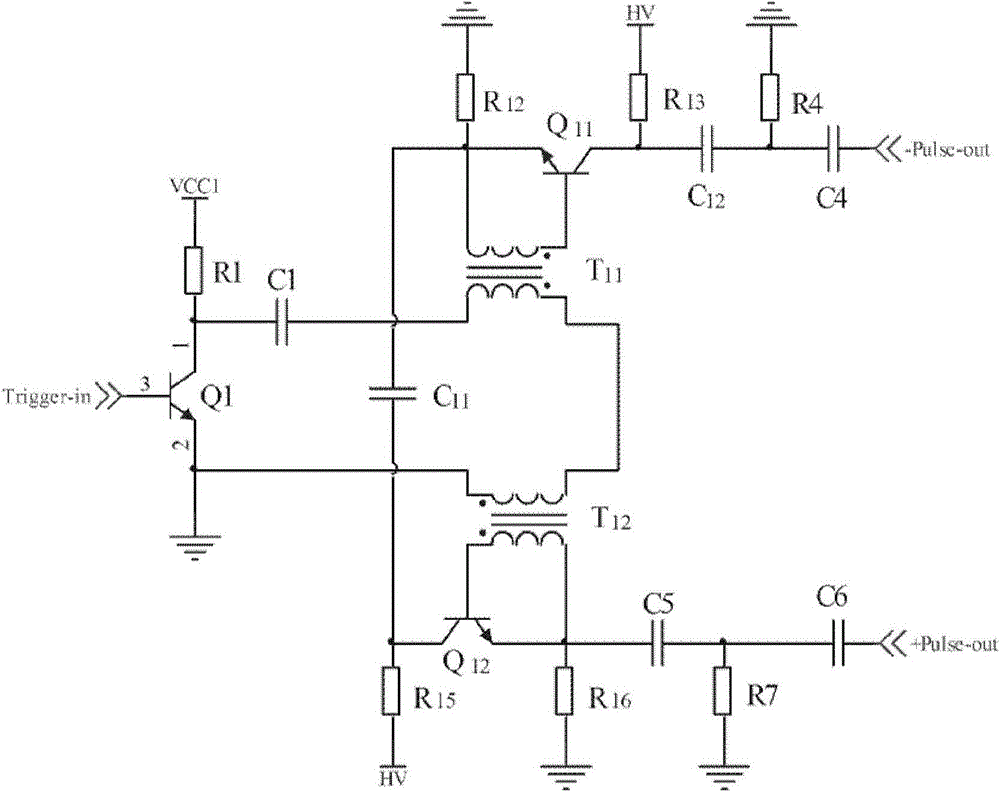
[0024] In the first exemplary embodiment of the present invention, a nanosecond balanced pulse signal generator is provided. figure 1 It is a schematic diagram of the structure of the pulse signal generator of the present invention. figure 2 It is a circuit diagram of a nanosecond balanced pulse signal generator according to the first embodiment of the present invention.

[0025] Please refer to figure 1 with figure 2 , The nanosecond balanced pulse signal generator of this embodiment includes: a trigger signal generating circuit for generating a trigger signal; a trigger signal shaping circuit, the front end of which is electrically connected to the trigger signal generating circuit for shaping the trigger signal; pulse The signal generating circuit, whose front end is electrically connected to the trigger signal shaping circuit, is used to trigger the generation of a nanosecond balanced pulse signal by using the shaped trigger pulse signal.

[0026] The components of the nanosec...

no. 3 example

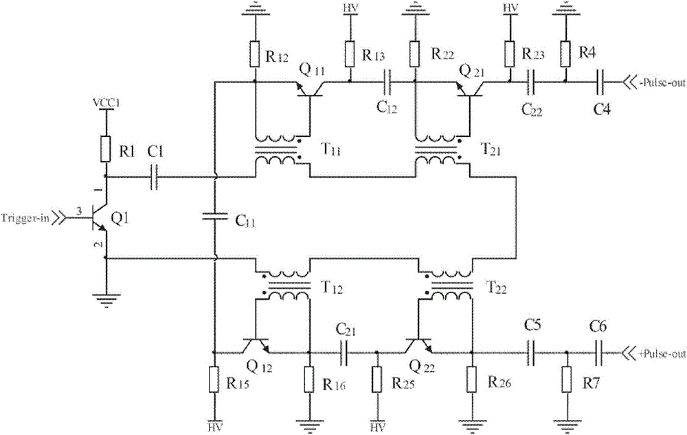
[0070] In the third exemplary embodiment of the present invention, a large amplitude femtosecond balanced pulse signal generator is provided. Figure 4 It is a circuit diagram of a large amplitude femtosecond balanced pulse signal generator according to the third embodiment of the present invention. Please refer to figure 1 with Figure 4 In this embodiment, on the basis of the second embodiment, a third amplification / reduction circuit unit and a fourth amplification / reduction circuit unit are added between the second amplification / reduction circuit and the coupling circuit. The four amplification and reduction circuit units together constitute an amplification and reduction module.

[0071] The structure of the two amplitude-increasing and widening circuit units is the same as the structure of the amplitude-increasing and widening circuit unit in the foregoing embodiment, and the detailed description is omitted here.

[0072] Please refer to Figure 4 , In the pulse signal gene...


PUM


Abstract

The invention provides an amplitude increasing and width reducing circuit unit and a pulse signal generating circuit and generator comprising the amplitude increasing and width reducing circuit unit. According to the amplitude increasing and width reducing circuit unit, two avalanche transistors which are cascaded are used as a basic unit circuit to construct the nanosecond balance pulse signal generator, and compared with a pulse generating circuit composed of a single avalanche transistor, pulse signals generated by the nanosecond balance pulse signal generator are large in amplitude, the pulse front edges are steep, and circuit reliability is high.

Description

Technical field [0001] The present invention relates to the field of electronic technology, in particular to an amplitude-increasing and decreasing circuit unit and a pulse signal generating circuit and generator using the same. Background technique [0002] Ultra-wideband technology is a wireless technology that uses sub-nanosecond or picosecond narrow pulse signals for data communication. It has high data transmission rate, high bandwidth, strong anti-multipath ability, low probability of interception and detection, and positioning High precision and other advantages, it can be effectively applied to wireless local area network, fluoroscopy imaging, precise positioning, non-destructive testing, medical systems (such as telemedicine services, non-contact detection of heartbeat and breathing), weapon control systems (such as anti-interference confidential military communications, navigation , Electronic countermeasures, large-scale ordnance collision avoidance, anti-terrorism com...

Claims


Application Information

Patent Timeline
Patent Type & Authority Patents(China)
IPC IPC(8): H03K5/13H03K5/01
Inventor 刘丽华夏新凡管洪飞张群英方广有
Owner INST OF ELECTRONICS CHINESE ACAD OF SCI
Learn More