

Thrust sliding bearing
A sliding bearing and thrust technology, used in sliding contact bearings, bearings, bearings in rotary motion, etc., can solve problems such as increased frictional resistance, achieve low friction performance, and achieve the effect of installation operation
- Summary
- Abstract
- Description
- Claims
- Application Information
AI Technical Summary
Problems solved by technology
Method used
Image

Examples
Embodiment Construction
[0061]In the following, the present invention will be described in more detail with reference to preferred embodiments shown in the accompanying drawings. It should be noted that the present invention is not limited to these Examples.
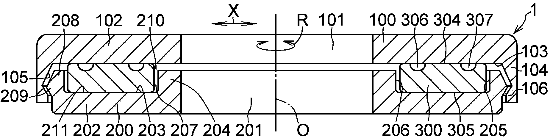
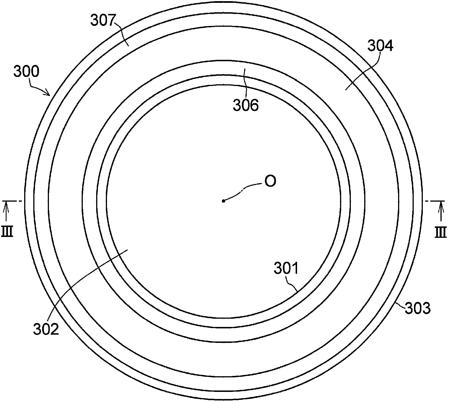
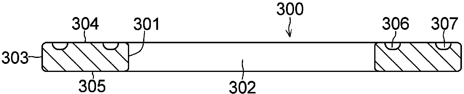
[0062] exist Figure 1 to Figure 5 , the thrust sliding bearing 1 according to the present embodiment includes an upper casing 100 made of synthetic resin, a lower casing 200 made of synthetic resin, and a thrust sliding bearing 300 made of synthetic resin provided between the upper casing 100 and the lower casing 200 .
[0063] The upper housing 100 includes: an upper annular flat portion 102 having a circular hole 101 at its central portion; a cylindrical engaging suspension portion 104 integrally formed on the cylindrical engaging suspension portion 104 on the outer periphery of the annular lower surface 103 of the upper annular flat portion 102 ;
[0064] The lower shell 200 stacked on the upper shell 100 so as to be able to rotate aroun...
PUM
 Abstract
Description
Claims
Application Information