Method for producing sliding bearing, and sliding bearing

A sliding bearing and structure technology, applied in the directions of shafts and bearings, bearing components, mechanical equipment, etc., can solve the problem of not being able to obtain the content of the cladding, and achieve the effect of improving adhesion strength, bonding strength, and adhesion.

Active Publication Date: 2014-09-17
MIBA SINTER AUSTRIA
View PDF9 Cites 7 Cited by
  • Summary
  • Abstract
  • Description
  • Claims
  • Application Information

AI Technical Summary

Problems solved by technology

But nothing can be drawn from this document about the cladding itself

Method used


Image

  • Method for producing sliding bearing, and sliding bearing
  • Method for producing sliding bearing, and sliding bearing
  • Method for producing sliding bearing, and sliding bearing

Examples


Embodiment Construction

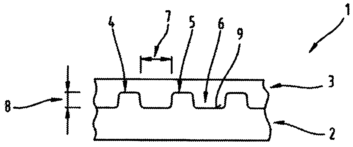
[0024] At the outset, it should be pointed out that the same components are provided with the same reference symbols or the same component designations in the different described embodiments, wherein the disclosure content contained in the entire description can be transferred to the components with the same reference symbols or the same component designations. on the same part. Likewise, positional indications selected in the description such as above, below, side, etc. relate to the directly described and illustrated figure and, in the event of a change in position, are sensibly transferred to the new position.

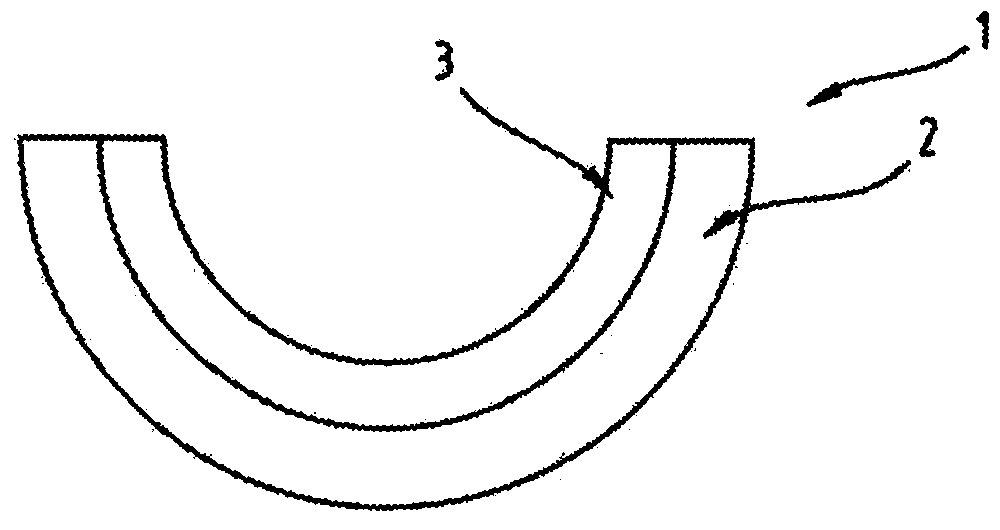
[0025] figure 1 A side view of the slide bearing 1 is shown. Plain bearing 1 comprises or consists of a carrier layer 2 and a plain bearing layer 3 .

[0026] In addition to the half-shell embodiment with an angular coverage of at least approximately 180°, non-closed plain bearings 1 can also have a different angular coverage, for example at least approximately 12...


PUM


Abstract

The invention relates to a method for producing a sliding bearing (1) comprising a supporting layer (2) and a sliding bearing layer (3), wherein the supporting layer (2) is connected to the sliding bearing layer (3) by way of roll bonding, and wherein prior to the roll bonding a surface structuring (4) is produced on the surface of the supporting layer (2) and the sliding bearing layer (3) is then rolled onto the surface structuring (4).

Description

technical field [0001] The invention relates to a method for producing a plain bearing comprising a support layer and a plain bearing layer, the support layer being connected to the plain bearing layer by means of rolling cladding (Walzplattieren); and the invention relates to a process comprising a support layer and a plain bearing layer Plain bearing of a plain bearing layer to which the carrier layer is connected. Background technique [0002] The use of babbitt metals for plain bearing layers, such as bearing metal layers or sliding layers, is extensively described in the prior art. See, for example, AT 505 664 B1 or AT 506 450 B1 in this respect. [0003] The deposition of babbitt on steel beams is usually carried out by pouring babbitt onto the beams, since the roll cladding (roll cladding) of steel and babbitt is based on very different deformations of the two joining partners Ability is difficult. [0004] Usually, an intermediate layer is inserted between the car...

Claims


Application Information

Patent Timeline
Patent Type & Authority Applications(China)
IPC IPC(8): F16C33/12
CPCF16C33/122F16C33/12
Inventor F·朗拜因L·黑蒂克M·霍尔青格
Owner MIBA SINTER AUSTRIA
Why Eureka
Try Eureka