
Flat bracket and electronic device

A technology of flat cables and conductors, which is applied in the direction of flat/ribbon cables, communication cables, insulated cables, etc., which can solve the problems that the space for coaxial cables cannot be guaranteed, and achieve the effect of small width and high reliability

Active Publication Date: 2014-09-17
MURATA MFG CO LTD
View PDF5 Cites 5 Cited by
  • Summary
  • Abstract
  • Description
  • Claims
  • Application Information

AI Technical Summary

Problems solved by technology

[0003] However, in recent years, the miniaturization and thinning of high-frequency equipment including mobile communication terminals have been progressing, and it may not be possible to secure a space for arranging coaxial cables in the terminal case.

Method used


Image

  • Flat bracket and electronic device
  • Flat bracket and electronic device
  • Flat bracket and electronic device

Examples


Embodiment Construction

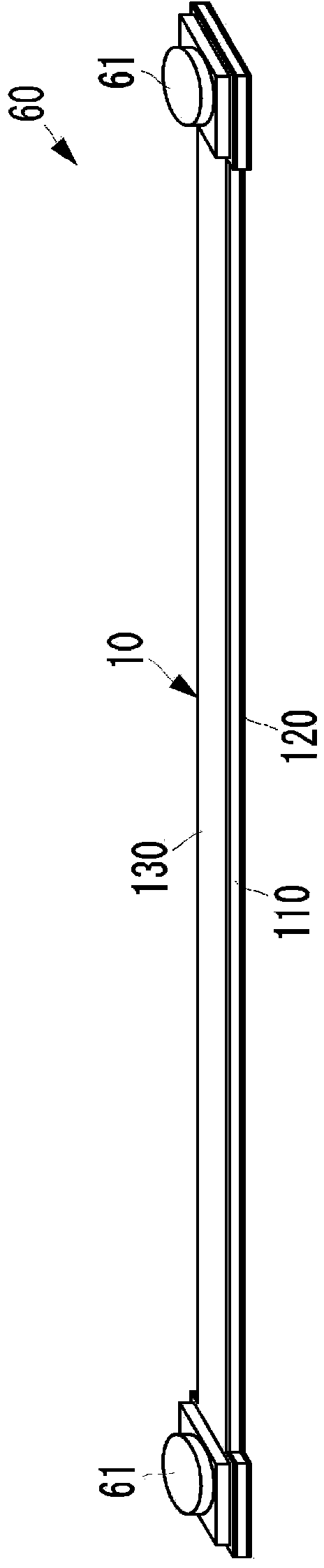
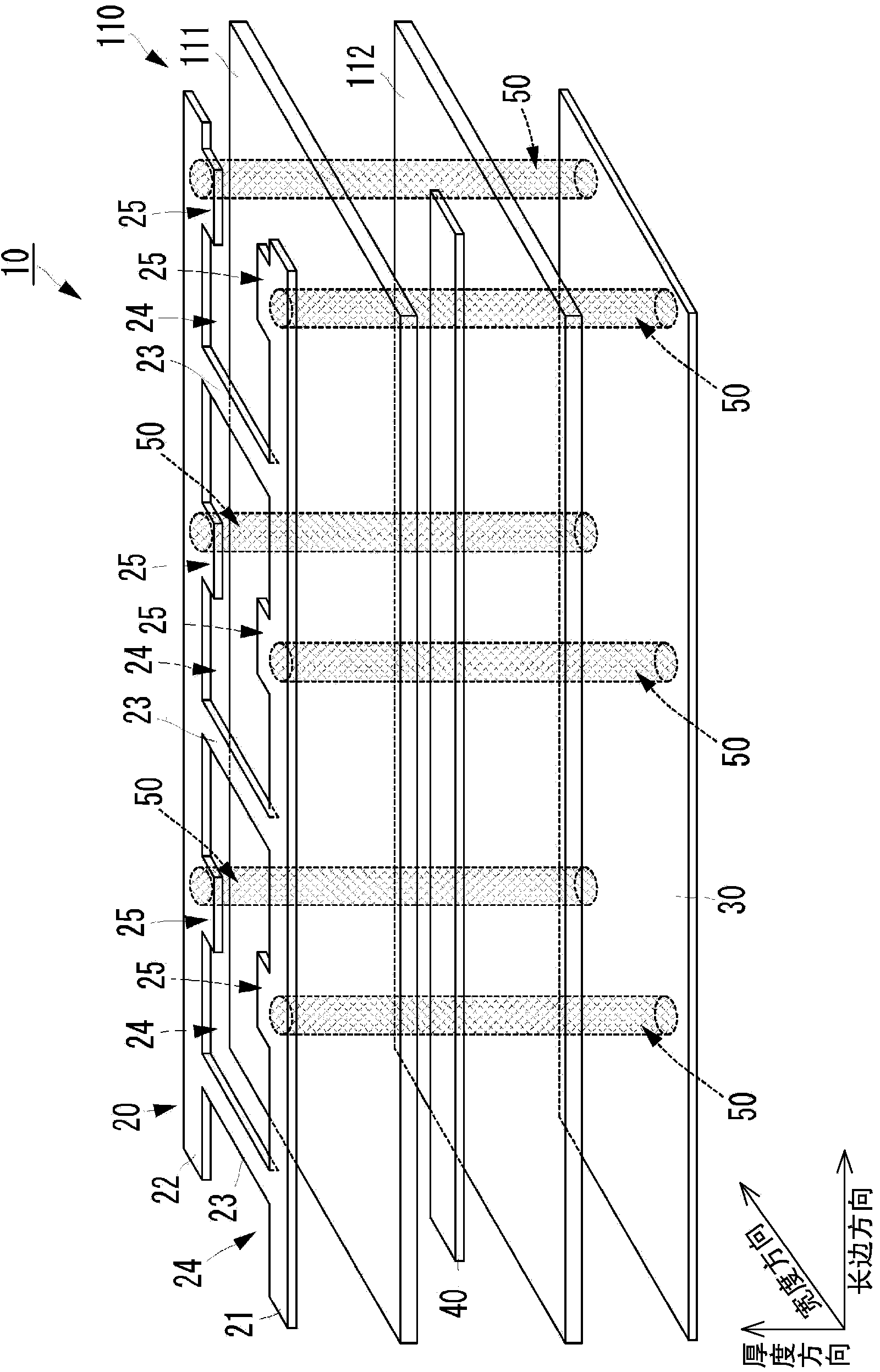
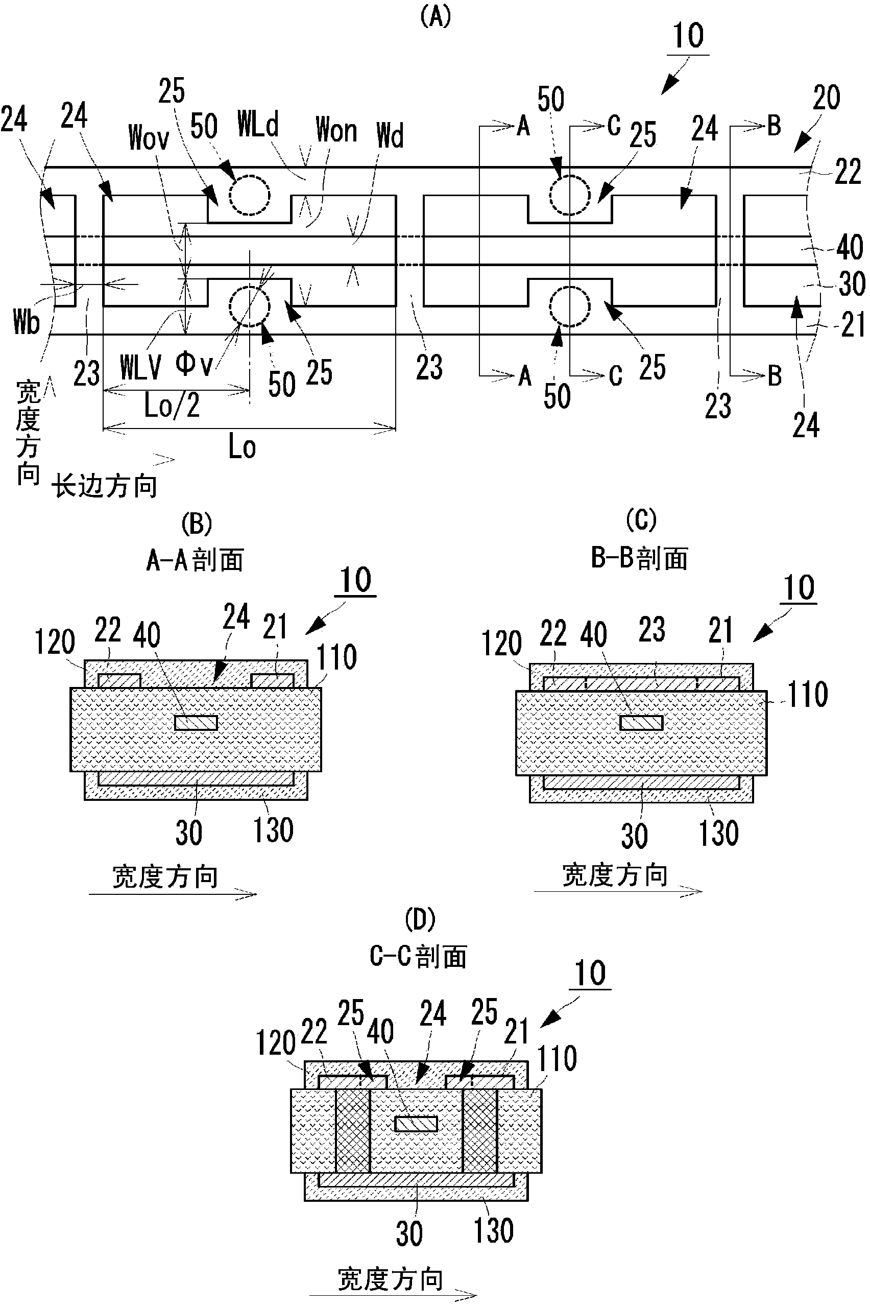
[0049] A flat cable according to Embodiment 1 of the present invention will be described with reference to the drawings. figure 1 It is an external perspective view of the flat cable 60 according to Embodiment 1 of the present invention. figure 2 It is an exploded perspective view showing a part of the transmission line unit. image 3 It is a top view and a sectional view which show a part of a transmission line part. image 3 (A) is a plan view when the transmission line part 10 is viewed from the first main surface side in a state where the dielectric main body 110 is omitted, image 3 (B) is image 3 A-A sectional view of (A), image 3 (C) is image 3 (A) B-B sectional view. image 3 (C) is image 3 (A) C-C sectional view. image 3 (A) is a plan view when the transmission line part 10 is seen from the 1st main surface side in the state which omitted the medium main body.

[0050] The flat cable 60 includes a transmission line portion 10 and a coaxial connector 61 ....


PUM


Abstract

A transmission line section of a flat cable includes a dielectric element including a signal conductor at an intermediate position of a thickness direction, a first ground conductor, and a second ground conductor. The first ground conductor includes elongated conductors that are spaced apart from each other in a width direction of the dielectric element, and extend in a longitudinal direction, and bridge conductors that connect the elongated conductors at spaced points along the longitudinal direction. A widened portion having a width larger than the width of the elongated conductors is located at the intermediate position between bridge conductors that are adjacent to each other along the longitudinal direction. The widened portion is configured to project in a direction in which the elongated conductors are opposed to each other. An interlayer connection conductor is located in the widened portion. The first ground conductor and the second ground conductor are connected by the interlayer connection conductor.

Description

technical field [0001] The present invention relates to a thin flat cable for transmitting a high-frequency signal and an electronic device including the flat cable. Background technique [0002] Conventionally, coaxial cables have been representative as high-frequency lines for transmitting high-frequency signals. A coaxial cable includes a central conductor (signal conductor) having a shape extending in one direction (a shape extending in a signal transmission direction), and shield conductors arranged concentrically along the outer peripheral surface of the central conductor. [0003] However, in recent years, miniaturization and thinning of high-frequency equipment including mobile communication terminals have been progressing, and there is a possibility that a space for arranging a coaxial cable in a terminal case cannot be secured. [0004] For such terminal housings, attention has been drawn to using such flat cables as disclosed in Patent Document 1 and Patent Docum...

Claims


Application Information

Patent Timeline
Patent Type & Authority Applications(China)
IPC IPC(8): H01B7/08H01B7/00H01B11/00H01P3/08H05K1/02
CPCH05K1/0221H05K1/147H01P5/028H01P3/085H01B7/0823H05K1/028H01B7/00H01B7/08H01B11/00H01P3/08H05K1/02
Inventor 加藤登
Owner MURATA MFG CO LTD
Features
  • Generate Ideas
  • Intellectual Property
  • Life Sciences
  • Materials
  • Tech Scout
  • Unparalleled Data Quality
  • Higher Quality Content
  • 60% Fewer Hallucinations
Learn More