Eureka AIR delivers breakthrough ideas for toughest innovation challenges, trusted by R&D personnel around the world.

Surface polishing machine

A technology for surface polishing and polishing discs, applied in the field of polishing machines, can solve problems such as inconvenience and hidden dangers to operator safety, and achieve the effects of simple operation, improved polishing efficiency and simple structure

Inactive Publication Date: 2014-09-24
CHENGDU KELIFU SCI & TECH
View PDF4 Cites 0 Cited by
  • Summary
  • Abstract
  • Description
  • Claims
  • Application Information

AI Technical Summary

Problems solved by technology

However, it adopts a hand-held polishing polishing machine, which needs to be held by the operator, which is very inconvenient, and it is also likely to bring safety hazards to the operator.

Method used


Image

  • Surface polishing machine

Examples


Embodiment

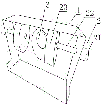
[0020] Such as figure 1 A surface polishing machine is shown, which includes an operation box 1 and two groups of polishing devices 2 fixed on the operation box 1. The operation box 1 is provided with an air exhaust port 3, and the air exhaust port 3 is located in the two groups Between the polishing devices 2 , the air exhaust port 3 is provided with an air exhaust device outside the operation box 1 . The draft device can be set as an exhaust fan or a draft device.

[0021] The polishing device 2 includes a driving device 21 , a connecting rod 22 fixed on the driving device 21 and a polishing disc 23 fixed on the connecting rod 22 .

[0022] The air intake 3 is located between two polishing discs 23 .

[0023] The drive device 21 is an electric motor.

[0024] The driving device 21 is respectively fixed on two corresponding surfaces of the operation box 1 , and the connecting rod 22 and the polishing disc 23 are both located in the operation box 1 .

[0025] The length of...


PUM

PropertyMeasurementUnit
Lengthaaaaaaaaaa

Abstract

The invention discloses a surface polishing machine which comprises a control box and two groups of polishing devices fixedly arranged on the control box, wherein the control box is provided with a suction opening; the suction opening is positioned between the two groups of polishing devices. The surface polishing machine has the advantages of simple structure, convenience in operation, double stations and polishing efficiency.

Description

technical field [0001] The present invention relates to a polishing machine, more particularly to a surface polishing machine for shoes. Background technique [0002] In the production process of shoes, in order to make it more beautiful when it leaves the factory and prolong the service life of the shoes, the surface of the shoes will be polished. Polishing the surface of shoes can be roughly divided into two processes, one is rough polishing and the other is fine polishing. The purpose of rough polishing is to remove the damaged layer produced during polishing. However, it adopts a hand-held polishing type polishing machine, which needs to be held by the operator, which is very inconvenient, and it is also easy to bring safety hazards to the operator. Contents of the invention [0003] The invention provides a surface polishing machine, which has a simple structure, is easy to operate, has double stations, and has high polishing efficiency. [0004] In order to solve ...

Claims


Application Information

Patent Timeline
IPC IPC(8): A43D95/08
Inventor 胡明容
Owner CHENGDU KELIFU SCI & TECH
Why Eureka
Eureka Blog
Learn More