

Preparation method for membrane electrode of fuel cell
A fuel cell membrane and electrode technology, applied in battery electrodes, circuits, electrical components, etc., can solve the problems of no large-scale use and short development time, and achieve the effect of improving utilization rate, improving interface structure, and smooth and uniform electrode structure
- Summary
- Abstract
- Description
- Claims
- Application Information
AI Technical Summary
Problems solved by technology
Method used
Image

Examples
Embodiment 1
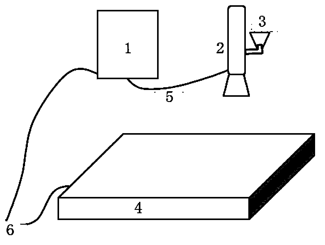
[0019] Take 10mg of 70% (the percentage of Pt in the total weight of the catalyst) Pt / C, 50mg of Nafion resin solution, and 10ml of isopropanol, and mix them uniformly to form a catalyst slurry. Adopt ordinary spray gun and electrostatic spray gun in the present invention respectively, spray above-mentioned slurry (spray distance, spray speed about 1ml / min, ambient temperature) to Nafion film surface, the effective area of spraying is 17.5cm 2 . When spraying with an electrostatic spray gun, place the Nafion film on a grounded platform, and the electrostatic generator controls the output voltage to 60kV, so that the slurry is charged with electrostatic charges. After spraying on the surface of the film, the electrostatic charges are guided away along the grounding wire.
[0020] The Pt loading test was carried out on the electrodes sprayed above. Cut an area of 2*2cm from the electrode sprayed above 2 Put the small pieces in a corundum crucible and roast at 850 ° for 2 h...
Embodiment 2
[0024] Take 24mg50% (the percentage of Pt in the total weight of the catalyst) Pt / C, 180mg Nafion resin solution, and 20ml isopropanol, and mix them uniformly to form a catalyst slurry. Adopt ordinary spray gun and electrostatic spray gun in the present invention respectively, spray above-mentioned slurry (spray distance, spray speed about 1ml / min, ambient temperature) to Nafion film surface, the effective area of spraying is 30cm 2 . When spraying with an electrostatic spray gun, place the Nafion film on a grounded platform, and the electrostatic generator controls the output voltage to 30kV, so that the slurry is charged with electrostatic charges. After spraying on the surface of the film, the electrostatic charges are guided away along the grounding wire.
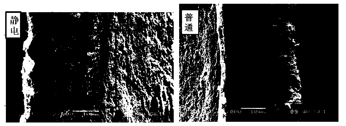
[0025] The above-mentioned sprayed electrode was cut with a scalpel, and the cross-sectional morphology of the electrode was observed with a scanning electron microscope, as shown in figure 2 shown. It can be seen ...
Embodiment 3
[0027] Take 57mg of 70% (Pt as a percentage of the total weight of the catalyst) Pt / C, 340mg of Nafion resin solution, and 30ml of isopropanol, and mix them uniformly to form a catalyst slurry. Adopt ordinary spray gun and electrostatic spray gun in the present invention respectively, spray above-mentioned slurry (spray distance, spray speed about 1ml / min, ambient temperature) to Nafion film surface, the effective area of spraying is 100cm 2 . When spraying with an electrostatic spray gun, place the Nafion film on a grounded platform, and the electrostatic generator controls the output voltage to 90kV, so that the slurry is charged with electrostatic charges. After spraying on the surface of the film, the electrostatic charges are guided away along the grounding wire.
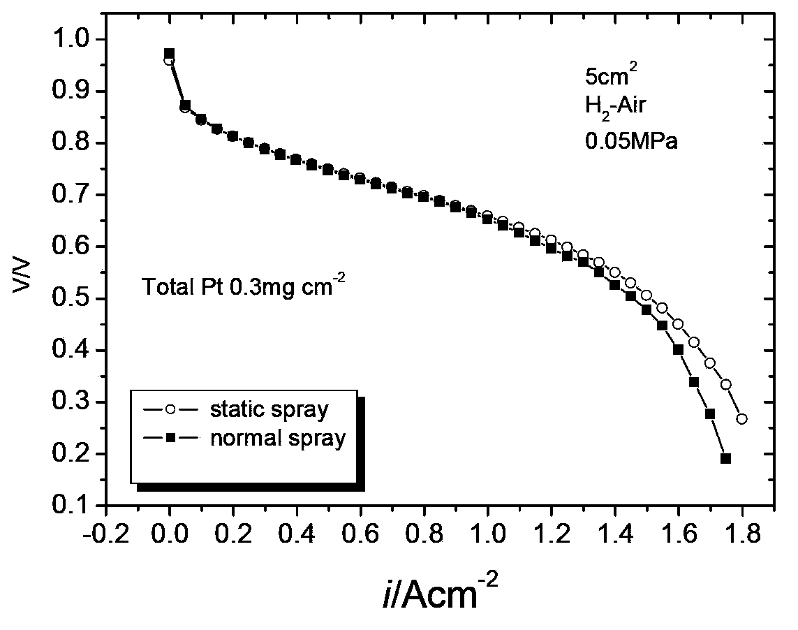
[0028] Press the two sprayed electrodes together with the gas diffusion layer to form an MEA, assemble the single cell, and perform a performance test after the cell is activated, such as image 3 shown. It...
PUM
 Abstract
Description
Claims
Application Information