An integrated bridge erecting machine and bridge erecting method for ultra-low transportation and erecting girders

A bridge erecting machine and rack transporting technology, which is applied in the field of ultra-low transport girder integrated bridge erecting machine and bridge erection, can solve the problems of unsuitable height limitation, influence on stability, complicated procedures, etc., and achieve simplified procedures and good adaptability. , the effect of improving efficiency

Active Publication Date: 2016-02-03
HEBEI UNIV OF TECH
View PDF7 Cites 0 Cited by
  • Summary
  • Abstract
  • Description
  • Claims
  • Application Information

AI Technical Summary

Problems solved by technology

[0002] At present, the existing integrated bridge erecting machine for transporting and erecting girders (abbreviated as all-in-one machine), such as a bridge erecting machine disclosed in Chinese utility model patent ZL200420115944. The front wheel set of the girder erecting machine can fall on the bridge surface, resulting in many procedures in the bridge erection process, time-consuming and laborious, and low efficiency, and its height limit is not suitable for bridge erection under special circumstances
At the same time, when erecting at the entrance and exit of the tunnel, due to the difference in height between the guide girder and the bridge abutment when the girder transporter and the guide girder frame girder are installed, it greatly affects the stability of the equipment, the smooth transition of the equipment load and the construction safety.
Another example is a bridge erecting machine disclosed in Chinese invention patent 201010119289, which only solves the problem of retreating of the guide beam during the erection process, but does not solve the problem of the forward extension of the guide beam. At the same time, its height reduction is very limited, and the front of the frame transporter is in contact with the support wheels of the frame transporter and slides relatively, which also affects the stability of its operation

Method used


Image

  • An integrated bridge erecting machine and bridge erecting method for ultra-low transportation and erecting girders
  • An integrated bridge erecting machine and bridge erecting method for ultra-low transportation and erecting girders
  • An integrated bridge erecting machine and bridge erecting method for ultra-low transportation and erecting girders

Examples


Embodiment Construction

[0057] Below in conjunction with the embodiment and accompanying drawings, the ultra-low transport girder integrated bridge erecting machine and the bridge erecting method of the present invention will be further described.

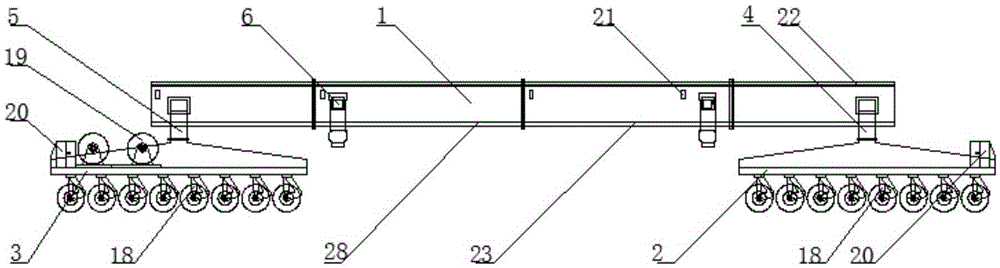
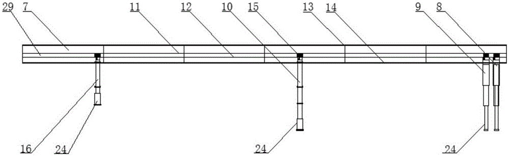
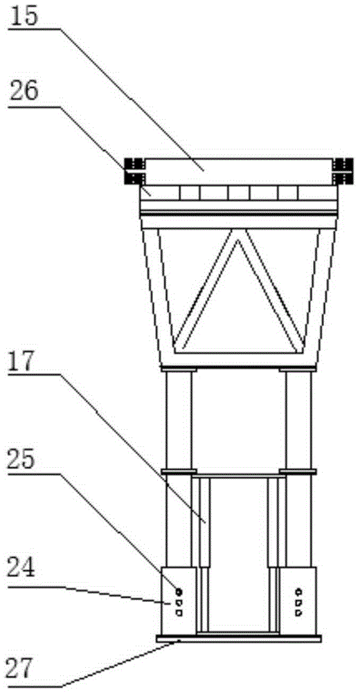
[0058] The ultra-low integrated bridge erecting machine designed by the present invention (abbreviated as the integrated machine, see Figure 1-5 ), the all-in-one machine includes a frame transporting beam machine and an upper guide beam machine, which is characterized in that the frame transporting beam machine includes a main beam 1 and front and rear traveling wheel sets 2,3, and front and rear traveling wheel sets 2,3 Each wheel set is equipped with a height adjustment oil cylinder 18, and the front and rear travel wheel sets 2, 3 are respectively equipped with front and rear support frames 4, 5, the front support frame 4 is rigidly connected with the side of the main beam 1, and the rear 5 supports The two ends of the frame and the main beam 1 are r...


PUM


Abstract

The invention discloses an ultralow frame beam conveying-integrated bridging machine and a bridging method thereof. The bridging machine comprises a frame beam conveying machine and an upper guide beam machine, and is characterized in that the frame beam conveying machine comprises a main beam, a front walking wheel group, a rear walking wheel group and a winch unit, wherein the front walking wheel group and the rear walking wheel group are respectively provided with a front support and a rear support; the two sides of the main beam are provided with hoisting mechanisms; the hoisting mechanisms are provided with front-and-rear movement micro-adjusting mechanisms; the winch unit is arranged in the rear walking wheel group; the upper guide beam machine comprises a guide beam, an auxiliary foldable landing leg, a front roller wheel foldable landing leg, a middle roller wheel foldable landing leg and a rear roller wheel foldable landing leg; the upper surface of the guide beam is provided with a sliding block rail, and the lower surface of the guide beam is provided with a sliding block; the guide beam is internally provided with a tackle guide rail and a groove; the tackle guide rail is provided with a landing leg tackle; the landing leg tackle is connected with the front roller wheel foldable landing leg, the middle roller wheel foldable landing leg and the rear roller wheel foldable landing leg; the landing leg tackle is provided with a braking mechanism and a driving motor. In the bridging method, the ultralow conveying frame beam integrated bridging machine is adopted, so that bridging is safely, efficiently and completely finished by virtue of nine steps.

Description

technical field [0001] The invention relates to bridge erecting machine technology, in particular to a bridge erecting machine integrated with ultra-low transportation and erecting girders and a bridge erecting method. Background technique [0002] At present, the existing integrated bridge erecting machine for transporting and erecting girders (abbreviated as all-in-one machine), such as a bridge erecting machine disclosed in Chinese utility model patent ZL200420115944. The front wheel set of the girder transporter can fall on the bridge surface, resulting in many procedures in the bridge erection process, time-consuming and laborious, and low efficiency, and its height limit is not suitable for bridge erection under special circumstances. At the same time, when erecting at the entrance and exit of the tunnel, due to the difference in height between the guide girder and the bridge abutment when the girder transporter and the guide girder frame girder are installed, it great...

Claims


Application Information

Patent Timeline
Patent Type & Authority Patents(China)
IPC IPC(8): E01D21/06
Inventor 陈子顺丁大龙张建辉李昊孙琪王诗伟张亚杰李孟欠
Owner HEBEI UNIV OF TECH
Why Eureka
Try Eureka