Thickness measuring probe

A technology of thickness measurement and probe emission, which is applied to measuring devices, instruments, and the use of ultrasonic/sonic/infrasonic waves, etc., can solve problems such as the impact of detection effects, achieve good sound insulation, thin thickness, and improve detection effects.

Inactive Publication Date: 2014-09-24
CHANGZHOU CHANGCHAO ELECTRONICS RES INSTCO
View PDF9 Cites 0 Cited by
  • Summary
  • Abstract
  • Description
  • Claims
  • Application Information

AI Technical Summary

Problems solved by technology

However, if the thickness of the sound insulation layer is reduced, the detection blind zone can indeed be reduced, but the detection effect will obviously be affected

Method used


Image

  • Thickness measuring probe
  • Thickness measuring probe

Examples


Embodiment Construction

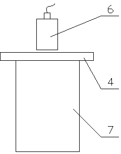
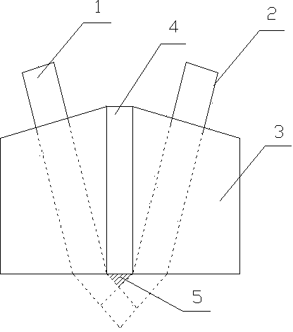
[0013] like figure 1 As shown, a thickness measuring probe includes a transmitting probe 1, a receiving probe 2 and two identical wedges 3, the two wedges 3 are separated by a sound insulation layer 4, and the two wedges 3 are opposite Mirroring the sound insulation layer 4, the top of each wedge 3 is an inclined surface, and the higher end of the inclined surface is close to the sound insulation layer 4, and the lower end of the inclined surface is far away from the sound insulation layer 4; the sound insulation layer 4 Vertical to the horizontal plane, the two inclined surfaces are symmetrical about the sound insulation layer 4, the transmitting probe 1 and the receiving probe 2 are arranged symmetrically on the inclined surface of the wedge 3 respectively, and the sound insulation layer 4 is polypropylene with a thickness of 0.4-0.5 mm.

[0014] Take the 0.5mm cork board as a comparative example to carry out a comparative test, such as figure 2 As shown, the sound insula...


PUM

PropertyMeasurementUnit
thicknessaaaaaaaaaa

Abstract

The invention relates to a thickness measuring probe. The thickness measuring probe comprises an emitting probe, a receiving probe and two same wedge blocks; the two same wedge blocks are isolated through a sound insulation layer and arranged opposite to the sound insulation layer by means of mirror; each wedge block is provided with an inclined surface on the top part; the higher end of the inclined surface is closed to the sound insulation layer and while the lower end of the inclined surface is away from the sound insulation layer; the sound insulation layer is vertical to the level; the two inclined surfaces are symmetrically arranged about the sound insulation layer; the emitting probe and the receiving probe are respectively symmetrically arranged on the inclined surfaces of the wedge blocks; the sound insulation layer is manufactured through polyethylene and 0.4 to 0.5mm in thickness. According to the thickness measuring probe, the sound insulation layer is manufactured through polyethylene, thus good heat insulation effect is realized, the thickness is small, nearly no detecting blind area is caused, and as a result, the probing result is improved.

Description

[0001] technical field [0002] The invention relates to the field of ultrasonic equipment, in particular to a thickness measuring probe. Background technique [0003] Ultrasonic flaw detection technology is widely used in industrial production, especially ultrasonic testing equipment for thickness measurement. In this equipment, due to the close distance between the two piezoelectric wafers, a sound insulation layer is set between the two probes to avoid interference. The sound waves used to block the transmitting probe are directly received by the receiving probe, affecting the detection effect. However, due to the additional sound insulation layer, blind spots appear in the detection area below the probe, which brings trouble to the detection. [0004] At present, in practical applications, the sound insulation effect is improved by increasing the thickness of the sound insulation layer, which will undoubtedly increase the detection blind area. However, if the thickness...

Claims


Application Information

Patent Timeline
Patent Type & Authority Applications(China)
IPC IPC(8): G01B17/02G01B1/00
Inventor 周南岐
Owner CHANGZHOU CHANGCHAO ELECTRONICS RES INSTCO
Why Eureka
Try Eureka