
Light Receiving Circuit

A technology of optical circuits and reset circuits, which is applied in the direction of measuring circuits, light-controlled amplifiers, electrical components, etc., can solve the problems of low sensitivity of light-receiving circuits, and achieve the effects of low price, low current consumption, and miniaturized price

Active Publication Date: 2014-09-24
SII SEMICONDUCTOR CORP
View PDF3 Cites 3 Cited by
  • Summary
  • Abstract
  • Description
  • Claims
  • Application Information

AI Technical Summary

Problems solved by technology

That is, the conventional light receiving circuit has a problem of low sensitivity

Method used


Image

  • Light Receiving Circuit
  • Light Receiving Circuit
  • Light Receiving Circuit

Examples


Embodiment Construction

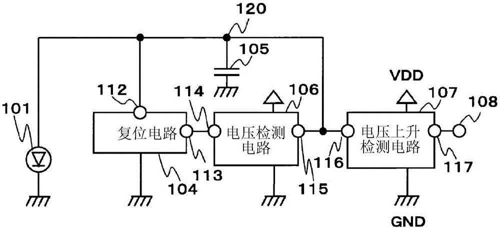
[0021] figure 1 It is a block diagram showing the light receiving circuit of this embodiment.

[0022] The light receiving circuit of this embodiment includes a photodiode 101 , a reset circuit 104 , a capacitor 105 , a voltage detection circuit 106 , and a voltage rise detection circuit 107 .

[0023] The N-type terminal of the photodiode 101 is connected to the GND terminal, and the P-type terminal is connected to the node 120 . The reset terminal 112 of the reset circuit 104 is connected to the node 120 , and the input terminal 113 is connected to the output terminal 114 of the voltage detection circuit 106 . One terminal of the capacitor 105 is connected to the node 120, and the other terminal is connected to the GND terminal. The input terminal 115 of the voltage detection circuit 106 is connected to a node 120 . The input terminal 116 of the voltage rise detection circuit 107 is connected to the node 120 , and the output terminal 117 is connected to the output termin...


PUM


Abstract

The invention relates to a light receiving circuit. The light receiving circuit includes: a photoelectric conversion element for causing a current corresponding to an amount of incident light to flow to a node; a voltage detection circuit for outputting a detection signal when a voltage of the node becomes equal to or higher than a first voltage; a reset circuit for causing, when the detection signal of the voltage detection circuit is input, the current of the photoelectric conversion element to flow to a GND terminal so that the voltage of the node becomes a second voltage lower than the first voltage, and for holding this state when the detection signal is no longer input; and a voltage increase detection circuit for detecting a fluctuation in the voltage of the node and outputting a detection result.

Description

technical field [0001] The present invention relates to a light receiving circuit that detects a change in light quantity, and in particular, relates to a light receiving circuit that can stably detect a change in light quantity regardless of surrounding brightness. Background technique [0002] The light receiving circuit is used for infrared long-distance communication or optical signal reception of visible light communication, photointerrupter or distance sensor, etc. As a function of this light receiving circuit, it is not necessary to detect a slow change in the light quantity due to the movement of a person or an object due to wind swings, or a light quantity change of a fluorescent lamp whose brightness fluctuates at a frequency of 50 Hz, but it is necessary to detect a sudden change in the light quantity when an LED is turned on. The amount of light changes. In addition, it is also important that the light receiving sensitivity does not vary with the surrounding bri...

Claims


Application Information

Patent Timeline
Patent Type & Authority Applications(China)
IPC IPC(8): G01S7/48H03F3/08
CPCH03K5/2472H03K5/153G01J1/44
Inventor 宇都宫文靖
Owner SII SEMICONDUCTOR CORP
Features
  • Generate Ideas
  • Intellectual Property
  • Life Sciences
  • Materials
  • Tech Scout
  • Unparalleled Data Quality
  • Higher Quality Content
  • 60% Fewer Hallucinations
Learn More