Junction device of circuit breaker, circuit breaker and circuit breaker assembly

A technology for wiring devices and circuit breakers, applied in the direction of protective switch terminals/connections, etc.

Active Publication Date: 2014-09-24
DELIXI ELECTRIC
View PDF5 Cites 12 Cited by
  • Summary
  • Abstract
  • Description
  • Claims
  • Application Information

AI Technical Summary

Problems solved by technology

[0004] Therefore, the technical problem to be solved by the present invention is to overcome the complex circuit breaker wiring in the prior art, time-consuming and laborious, inconvenient to install, and high cost technology Problems, thus providing a wiring device that saves time and effort during installation, is efficient and convenient, has low cost, and is more economical to produce and use
[0005]Another technical problem to be solved by the present invention is to overcome the technical problems of complicated circuit breaker wiring in the prior art, time-consuming and laborious, inconvenient installation, and high cost , so as to provide a circuit breaker that saves time and effort in the installation process, is efficient and convenient, and has a lower cost and is more economical to produce and use
[0006]Another technical problem to be solved by the present invention is to overcome the technical problems of complicated circuit breaker wiring in the prior art, time-consuming and laborious, inconvenient installation, and high cost , so as to provide a time-saving, labor-saving, efficient and convenient installation process, and lower cost, more economical production and use of circuit breaker components

Method used


Image

  • Junction device of circuit breaker, circuit breaker and circuit breaker assembly
  • Junction device of circuit breaker, circuit breaker and circuit breaker assembly
  • Junction device of circuit breaker, circuit breaker and circuit breaker assembly

Examples


Embodiment 1

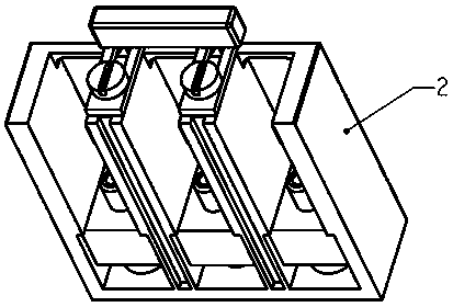
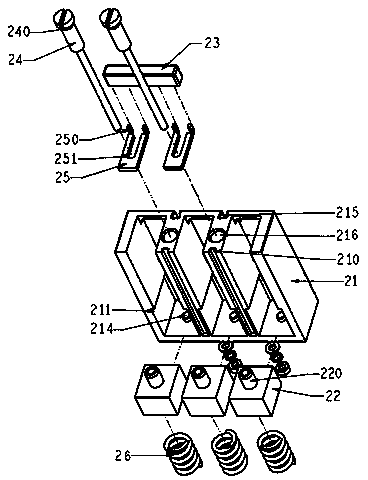
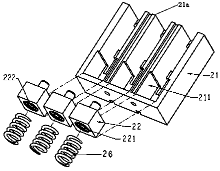
[0045] like Figure 1-2 As shown, the wiring device 2 of the molded case circuit breaker of this embodiment includes a terminal block 21 for realizing the electrical connection between the circuit breaker body and the cable. It includes a notch 212 at the top and a slot 211 communicating with the notch 212, and the outer wall of the terminal block 21 facing the insertion direction of the cable terminal 3 is provided with a card slot 215, and the card slot 215 is provided with For the arc shield, an elastic piece is arranged in the installation groove, and the elastic piece is installed in the installation groove through a fixing assembly, and the elastic piece has a mounting part. In this embodiment, the mounting part It is a boss 220, and the installation part can be respectively connected with the circuit breaker body 1 and the cable terminal 3 inserted into the installation groove, and a ridge 21a is formed between adjacent installation grooves, and a circuit breaker is arr...

Embodiment 2

[0054] like Figure 7 As shown, this embodiment provides a circuit breaker that can be used in conjunction with the wiring device described in Embodiment 1, including a circuit breaker body 1, and several protruding terminal blocks 10 are arranged on the circuit breaker body 1. The wiring board 10 is suitable for being inserted into the installation groove of the wiring device 2 in Embodiment 1. The wiring board 10 is provided with a wiring part 11, and the wiring part 11 is inserted into the installation groove after the wiring board 10 is inserted into the installation groove. It is suitable for socketing or inserting cooperation with any of the installation parts described above to fix the cable terminal inserted into the installation groove.

[0055] In this embodiment, the cover of the circuit breaker body 1 is provided with a snap-in groove 13 for sliding insertion of the sliding part 25, and the setting of the snap-in slot 13 facilitates the installation and connection ...

Embodiment 3

[0058] like Figure 7-9 As shown, the circuit breaker assembly of this embodiment includes a circuit breaker, a cable, and a wiring device 2 for realizing the electrical connection between the circuit breaker and the cable, and the wiring device 2 is the wiring device described in Embodiment 1 2. The circuit breaker is the circuit breaker described in Embodiment 2.

[0059] In this embodiment, the terminal board 10 is arranged opposite to the two sides of the circuit breaker body. The ridge 21a is provided with a groove 210 on the side wall facing the circuit breaker body, and the rib 12 on the outer wall of the circuit breaker is fitted into the groove 210, and the rib 12 is fitted into the groove 210. The cooperating arrangement of the rib 12 and the groove 210 makes the installation between the circuit breaker and the terminal block 21 more firm, avoids relative positional movement when the external shock occurs, and further improves the stability of the mechanism, and ado...


PUM


Abstract

The invention provides a junction device. The junction device comprises a wire holder, a plurality of installing grooves arranged side by side are formed in the wire holder, and springing pieces are arranged in the installing grooves and installed in the installing grooves through fixing assemblies. Each springing piece is provided with an installing part, wherein the installing part can be respectively connected with a circuit breaker body plugged into the corresponding installing groove and a cable terminal. A ridge is formed between every two adjacent installing grooves and provided with a circuit breaker body positioning assembly. Each circuit breaker body positioning assembly comprises a sliding piece and a fixing piece for fixing the positioning assembly to the corresponding ridge, wherein the sliding piece can slide along the ridge so as to be fixedly connected in a plugged mode or separated from the corresponding circuit breaker body. The device solves the technical problems that in the prior art, the operation of connection between a circuit breaker and a cable is complex, and time and labor are wasted, avoids the phenomenon that when installing the circuit breaker, a user uses a large number of screws to connect the circuit breaker and the cable, and is convenient for the user to use.

Description

Technical field [0001] The invention involves a wiring device, circuit breaker and circuit breaker component of a plastic shell circuit breaker, which belongs to the field of circuit breaker technology. Background technique [0002] In existing technology, such as Figure 10 and Figure 11 It is shown that the plastic shell broken circuit breaker does not have a dedicated wiring device. When installing the circuit breaker, the user needs to connect the cable to the circuit breaker body by screw or bolt.One, 8 pieces, more parts, high costs, and dedicated operating tools, large workloads, and inconvenient operations during the installation process. Especially when the plastic shell breakfire of the settings is installed, the circuit breaker is broken, and the circuit breakerThe installation volume is very large, a lot of time is wasted on the product wiring, and if the product is damaged in use, when the new product needs to be replaced, the old screw must be removed first. After th...

Claims


Application Information

Patent Timeline
Patent Type & Authority Applications(China)
IPC IPC(8): H01H71/08
Inventor 刘云飞叶青倪加岚李慧瑾孙刚
Owner DELIXI ELECTRIC
Why Eureka
Try Eureka