
A radiation-type leakage cable laying device and method with a protective device

A leaky cable and protective device technology, applied in the direction of cable laying equipment, etc., can solve the problems of small radiation field strength of leaky cables, no consideration of the influence of vibration and impact load of leaky cables and clips, damage of leaky cables, etc., and achieve strong radiation field , small fluctuation, fast installation effect

Active Publication Date: 2017-09-22
通号(郑州)轨道交通科技有限公司 +1
View PDF1 Cites 0 Cited by
  • Summary
  • Abstract
  • Description
  • Claims
  • Application Information

AI Technical Summary

Problems solved by technology

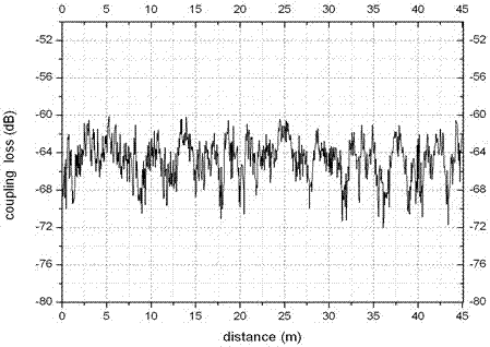
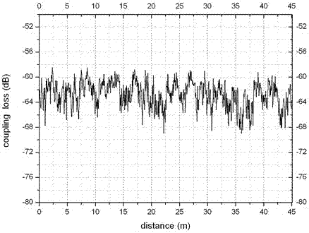
[0021] The deficiencies in the way of laying leaky cables in the tunnels of existing urban rail transit wireless communication systems: From the above analysis of the budget analysis of leaky cable links in the way of laying leaky cables in existing tunnels, it can be seen that the higher the frequency of use of leaky cables in existing tunnels, The radiation field strength of the leaky cable will be smaller under the same coverage distance (for example, 500 meters)
The leaky cable stipulated in this patent is fixed on the inner waist edge of the rail through clips. It is close to the rail. The electromagnetic waves radiated by the leaky cable are easily affected by the rail, and the vibration of the leaky cable and the clip during the high-speed operation of the train is not considered. and impact load, and did not take into account that in this laying environment, the leaky cable is extremely vulnerable to damage by external forces, such as people's trampling, the impact of falling heavy objects, etc.

Method used


Image

  • A radiation-type leakage cable laying device and method with a protective device
  • A radiation-type leakage cable laying device and method with a protective device
  • A radiation-type leakage cable laying device and method with a protective device

Examples


Embodiment approach 1

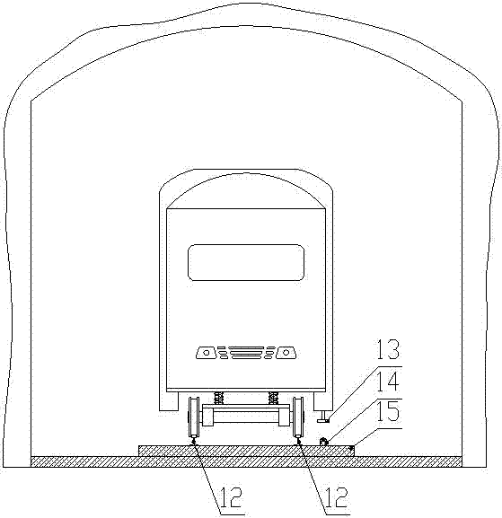
[0065] Such as Figure 5 As shown, the leaky cable fixing system 14 of the present invention is fixed in the area between the two steel rails 12 (inside the steel rail 12), and the leaky cable (ie, the radial leaky cable 5) is laid along the direction of the steel rail 12.

Embodiment approach 2

[0067] Such as Image 6 As shown, the leaky cable fixing system 14 of the present invention is fixed outside the two steel rails 12, and the leaky cable is laid along the track direction.

[0068] The leaky cable fixing system 14 has the function of directional leaky cable notch, which ensures that the notch of the leaky cable faces the direction of the on-board antenna, and the on-board antenna 13 is installed on the bottom of the train body. The laying height of the leaky cable fixing system 14 of the present invention should be lower than the rail surface height of the steel rail 12. After laying, the leaky cable axis is 8-12cm from the track concrete floor 15 and the distance between the vehicle antenna and the leaky cable is kept below 50cm.

[0069] The laying method of radiation leaky cable with protective device of the present invention:

[0070] The first step: first install the leaky cable fixing system 14 outside or inside the two steel rails 12. The leaky cable fixing sys...


PUM


Abstract

A radiation-type leaky cable laying device with a protective device, including a leaky cable fixing system, the leaky cable fixing system is installed under the train body and on the ground next to the rails, and the height of the leaky cable fixing system is lower than the rail surface height of the rails , the layout direction of the leaky cable fixing system is the same as the extension direction of the rail, the vehicle-mounted antenna is installed at the bottom of the train body, the leaky cable fixing system is located below the vehicle-mounted antenna, and the position of the vehicle-mounted antenna corresponds to the position of the leaky cable fixing system; The leaky cable fixing system includes a first part and a second part. The first part is detachably connected to the second part. Both the first part and the second part are in the shape of a shell. The first part is equipped with a non-metallic clamp for fixing the leaky cable. The second part is connected to the ground by expansion bolts. The invention is a new method for laying tunnel leaky cables in urban rail transit wireless communication systems, and can well solve the problem of low field strength of tunnel leaky cables in existing urban rail transit wireless communication systems, thereby prolonging the length of the leaky cables. coverage distance.

Description

Technical field [0001] The invention relates to a coaxial cable laying device and method. Background technique [0002] With the rapid development of my country's national economy, major domestic capital cities are vigorously developing and constructing urban rail transit. The rapid development of urban rail transit has made more and more applications place higher requirements on wireless communication systems. The urban rail transit wireless communication system is divided into a dedicated wireless communication system and a public wireless communication system. The dedicated wireless communication system includes wireless dispatch communication system, train control information vehicle-ground wireless transmission system, mobile TV system, public security wireless, fire wireless emergency communication system, mobile TV system, passenger guidance information system, etc. The public wireless communication system includes 2G, 3G, WIFI and 4G wireless signals of the three major o...

Claims


Application Information

Patent Timeline
Patent Type & Authority Patents(China)
IPC IPC(8): H02G1/06
Inventor 王胜军尚爱民王永青
Owner 通号(郑州)轨道交通科技有限公司
Learn More