Phase difference film, circularly polarizing plate using same, and image display device
A technology of retardation film and retardation value, which is applied in the direction of polarizing elements, lighting devices, applications, etc., can solve the problems of unevenness, reduction, and non-elimination of difficulty in forming roll film stretching processing, etc. Small, less image quality degradation
- Summary
- Abstract
- Description
- Claims
- Application Information
AI Technical Summary
Benefits of technology
Problems solved by technology
Method used
Image
Examples
Embodiment
[0304] Hereinafter, although an Example demonstrates this invention in more detail, this invention is not limited to the following Example unless the summary is exceeded.
[0305] Hereinafter, the characteristic evaluation of polycarbonate resin, polycarbonate resin composition, roll film, and retardation film was performed by the following method. In addition, the characteristic evaluation method is not limited to the following method, Those skilled in the art can select suitably.
[0306] [Evaluation of polycarbonate resin and polycarbonate resin composition]
[0307] (1) Photoelastic coefficient
[0308]
[0309] Using a spacer with a width of 8cm, a length of 8cm, and a thickness of 0.5mm, vacuum-dry at 80°C for 5 hours with a hot press at a hot pressing temperature of 200-250°C, preheating for 1-3 minutes, and a pressure of 20MPa. 4.0 g of the polycarbonate resin sample was pressurized for 1 minute, then taken out together with the spacer, and pressurized and cooled a...
Synthetic example 1
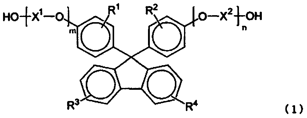
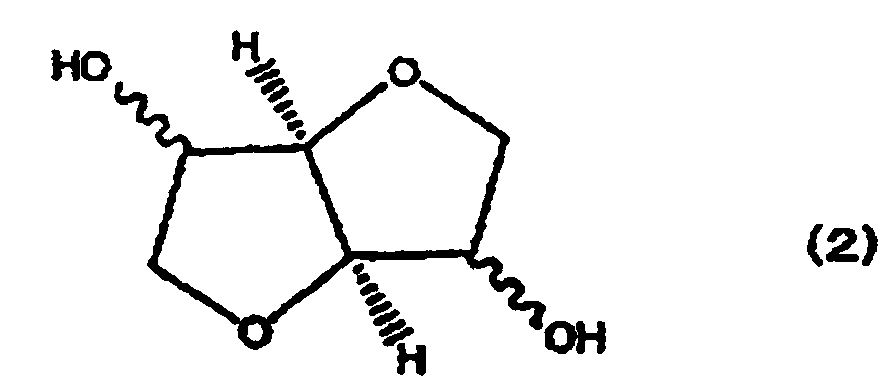
[0364] 445.1 parts by weight of isosorbide (hereinafter, sometimes abbreviated as "ISB"), 906.2 parts by weight of 9,9-(4-(2-hydroxyethoxy)phenyl) fluorene (hereinafter, sometimes abbreviated as "BHEPF") 15.4 parts by weight of polyethylene glycol with a molecular weight of 1000 (hereinafter, sometimes abbreviated as "PEG#1000"), 1120.4 parts by weight of diphenyl carbonate (hereinafter, sometimes abbreviated as "DPC"), and cesium carbonate as a catalyst ( 0.2% by weight aqueous solution) 6.27 parts by weight are dropped into the reactor, under nitrogen atmosphere, as the operation of the first stage of reaction, make the heat medium temperature of reaction container be 150 ℃, make raw material dissolve while stirring as needed (about 15 minute). Next, the pressure in the reaction vessel was changed from normal pressure to 13.3 KPa, and the temperature of the heating medium in the reaction vessel was raised to 190° C. over 1 hour, while the generated phenol was extracted out o...
Synthetic example 2
[0367] In Synthesis Example 1, 489.7 parts by weight of ISB, 856 parts by weight of BHEPF, 16 parts by weight of PEG#1000, 1162.2 parts by weight of DPC, and 6.5 parts by weight of cesium carbonate aqueous solution as a catalyst were used. Synthesis example 1 was carried out similarly, and the polycarbonate resin B of BHEPF / ISB / PEG#1000=36.7 mol% / 63.0 mol% / 0.3 mol% was obtained.
PUM
| Property | Measurement | Unit |
|---|---|---|
| Thickness | aaaaa | aaaaa |
Abstract
Description
Claims
Application Information
 - R&D
- Intellectual Property
- Life Sciences
- Materials
- Tech Scout
- Unparalleled Data Quality
- Higher Quality Content
- 60% Fewer Hallucinations
Browse by: Latest US Patents, China's latest patents, Technical Efficacy Thesaurus, Application Domain, Technology Topic, Popular Technical Reports.
© 2025 PatSnap. All rights reserved.Legal|Privacy policy|Modern Slavery Act Transparency Statement|Sitemap|About US| Contact US: help@patsnap.com


