Brake control unit for railway vehicle

A brake control and rail vehicle technology, which is applied in the field of vehicle brake control systems, can solve problems such as the inability to uniformly distribute the braking force of the entire vehicle, the inability to distribute the braking force in a balanced manner, and the loss of braking force distribution of the entire vehicle. Safety, improved safety level, improved equipment and reliability effects

Active Publication Date: 2014-10-01
NANJING CRRC PUZHEN HAITAI BRAKE EQUIP CO LTD
View PDF6 Cites 62 Cited by
  • Summary
  • Abstract
  • Description
  • Claims
  • Application Information

AI Technical Summary

Benefits of technology

This patented technology allows for better performance and efficiency during vehicles' operation compared to existing systems that use separate components like individual wheel sensors and hydraulic pressure regulators. It also includes redundancy between different levels of regulation such as train-to-train and section-based regulations. Additionally, there may be other functions provided separately from this module called Anti-Slip Control(ASC), which helps prevent slippages caused by excessive tire wear without affecting safe driving behavior. Overall, these technical features help ensure safer and more reliable automobile operations while ensuring efficient energy utilization.

Problems solved by technology

This patented technical problem addressed in this patents relates to improving the performance and reliability of EBCO units that are currently available but lacking any functionality related to their ability to accurately distribute and manage different types of forces during operation without losing its effectiveness due to failure modes such as lockup caused by incorrect wheel alignment.

Method used


Image

  • Brake control unit for railway vehicle

Examples


Embodiment Construction

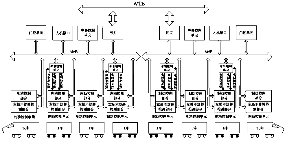
[0023] The technical solution of the present invention will be further described in conjunction with the accompanying drawings.

[0024] The overall structure distribution of the control unit of the present invention is as follows: figure 1 As shown, including the brake control part and the non-rotation detection part of the axle, these two parts are completely independent electrically. The brake control part mainly includes the air brake control unit, wheel slide protection unit, MVB network communication and serial communication, and the axle non-rotation detection part mainly includes the axle speed abnormal detection unit, MVB network communication and serial communication.

[0025] The brake control part has the function of brake force control. The braking force is calculated according to the vehicle load and speed information, and the braking force is managed and distributed through the MVB network. The motor vehicle applies for electric braking force to the traction c...


PUM


Abstract

The invention discloses a brake control unit for a railway vehicle. The brake control unit comprises a brake control part and an axle non-rotation detection part which are electrically independent of each other. The brake control part comprises a pneumatic brake control unit, a wheel sliding protection unit, an MVB network communication port and a serial port communication port. The axle non-rotation detection part comprises an axle speed anomaly detection unit, an MVB network communication port and a serial port communication port. The pneumatic brake control unit can conduct brake instruction receiving, brake force calculating, EP current control, EP current lag compensation control and the like. The wheel sliding protection module can conduct sliding and locking detection, sliding prevention and locking prevention control, tread sweeping control and ATC axle sliding state output. The axle speed anomaly detection unit judges whether a certain axle is locked or not or whether the speed of the axle is abnormal or not. The independent axle non-rotation detection part is arranged in the brake control unit, and therefore the working current of a speed sensor can be independently monitored and reported to a vehicle diagnosis device, and the safety level of the brake control unit is increased.

Description


Claims


Application Information

Patent Timeline
Owner NANJING CRRC PUZHEN HAITAI BRAKE EQUIP CO LTD
Why Eureka
Try Eureka