Splitter for rock boring

A splitter and rock technology, applied in the direction of discharge machinery, earthwork drilling and mining, etc., can solve the problems of low efficiency, difficult manual work, unsafe explosive blasting methods, etc., and achieve the effect of improving efficiency and better splitting effect

Active Publication Date: 2014-10-01
HENR TECH GUANGXI CO LTD
View PDF7 Cites 13 Cited by
  • Summary
  • Abstract
  • Description
  • Claims
  • Application Information

AI Technical Summary

Problems solved by technology

[0002] At present, in the non-blasting rock mining construction, there are mainly three mining methods: 1. Direct excavation with a breaker; 2. Putting an expansion agent after drilling to realize static blasting; Through the principle of inclined wedge amplification, the action of pushing two splitting blocks to split the rock is split. Although these methods avoid the unsafe explosive blasting method, they have the problems of low efficiency, difficult manual operation, and poor splitting effect; The patent "hydraulic splitting trolley" with the application number "201110070918.X" and the patent "hydraulic vibration rock splitter" with the application number "201010141572.3", these two patents installed the rock splitting equipment on the excavator and solved the problem of The problem of manual work is difficult and labor-intensive, but it is still necessary to replace the drilling rig on the excavator, replace it with a rock splitter, reposition it, and then split it. The problem of low efficiency has not been resolved

Method used


Image

  • Splitter for rock boring
  • Splitter for rock boring
  • Splitter for rock boring

Examples


Embodiment Construction

[0024] The present invention will be described in detail below in conjunction with the accompanying drawings and embodiments.

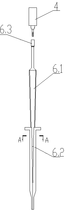
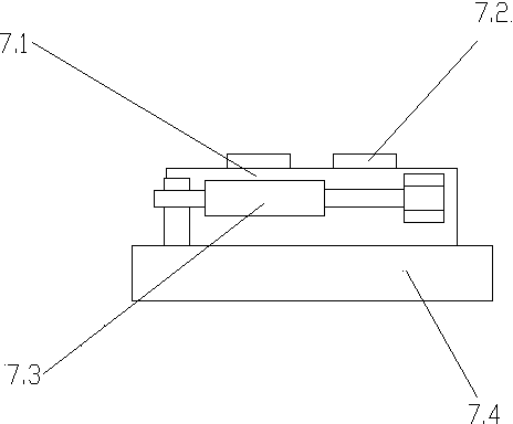
[0025] Such as Figure 1~Figure 8 As shown, the rock drilling splitter of the present invention includes a chassis 1, a boom 2, a small arm 3 and a control system, and also includes a propulsion beam 9, a hydraulic rock drill 4, a propulsion cylinder 12, a splitter 6 and a switching mechanism, and the propulsion beam 9 The middle part of the arm and the end of the forearm 3 are connected by an angle adjustment device 11, the propulsion beam 9 is set into a ∏ shape, a guide rail is set on the propulsion beam 9, the hydraulic rock drill 4 slides on the guide rail, the propulsion cylinder 12 is arranged in the Π shape, and the propulsion cylinder 12 is connected with the hydraulic rock drill 4, that is, the propulsion cylinder 12 drives the hydraulic rock drill 4 to slide on the guide rail, the switching mechanism is located on the side of the propelling...


PUM


Abstract

The invention discloses a splitter for rock boring, which comprises a chassis, a large arm, a small arm and a control system, and is characterized by further comprising a propelling beam, a hydraulic rock drill, a propelling oil cylinder, a splitting machine and a switching mechanism, wherein the propelling beam is connected with one end of the small arm through an angle adjusting device; both the hydraulic rock drill and the propelling oil cylinder are arranged on the propelling beam; the propelling oil cylinder drives the hydraulic rock drill to slide on the propelling beam; the switching mechanism is connected to one side edge of the propelling beam; the splitting machine is arranged on the switching mechanism. The splitter is high in efficiency and high in splitting effect.

Description

technical field [0001] The invention relates to the technical field of engineering machinery, in particular to a rock drilling splitter suitable for non-blasting rock mining, building dismantling and other constructions. Background technique [0002] At present, in the non-blasting rock mining construction, there are mainly three mining methods: 1. Direct excavation with a breaker; 2. Putting an expansion agent after drilling to realize static blasting; Through the principle of inclined wedge amplification, the action of pushing two splitting blocks to split the rock is split. Although these methods avoid the unsafe explosive blasting method, they have the problems of low efficiency, difficult manual operation, and poor splitting effect; The patent "hydraulic splitting trolley" with the application number "201110070918.X" and the patent "hydraulic vibration rock splitter" with the application number "201010141572.3", these two patents installed the rock splitting equipment o...

Claims


Application Information

Patent Timeline
Patent Type & Authority Applications(China)
IPC IPC(8): E21C37/08
Inventor 唐忠盛
Owner HENR TECH GUANGXI CO LTD
Why Eureka
Try Eureka