Actuation device with rotation-proof retaining nut

A technology of operating device and nut, applied in the direction of valve operation/release device, nut, valve device, etc., can solve problems such as current temperature fluctuation

Inactive Publication Date: 2014-10-01
ROBERT BOSCH GMBH
View PDF1 Cites 0 Cited by
  • Summary
  • Abstract
  • Description
  • Claims
  • Application Information

AI Technical Summary

Problems solved by technology

[0003] A disadvantage of the known actuating device is that the plastic housing is subject to extreme temperature fluctuations due to the current flowing in the coil with varying intensity

Method used


Image

  • Actuation device with rotation-proof retaining nut
  • Actuation device with rotation-proof retaining nut
  • Actuation device with rotation-proof retaining nut

Examples


Embodiment Construction

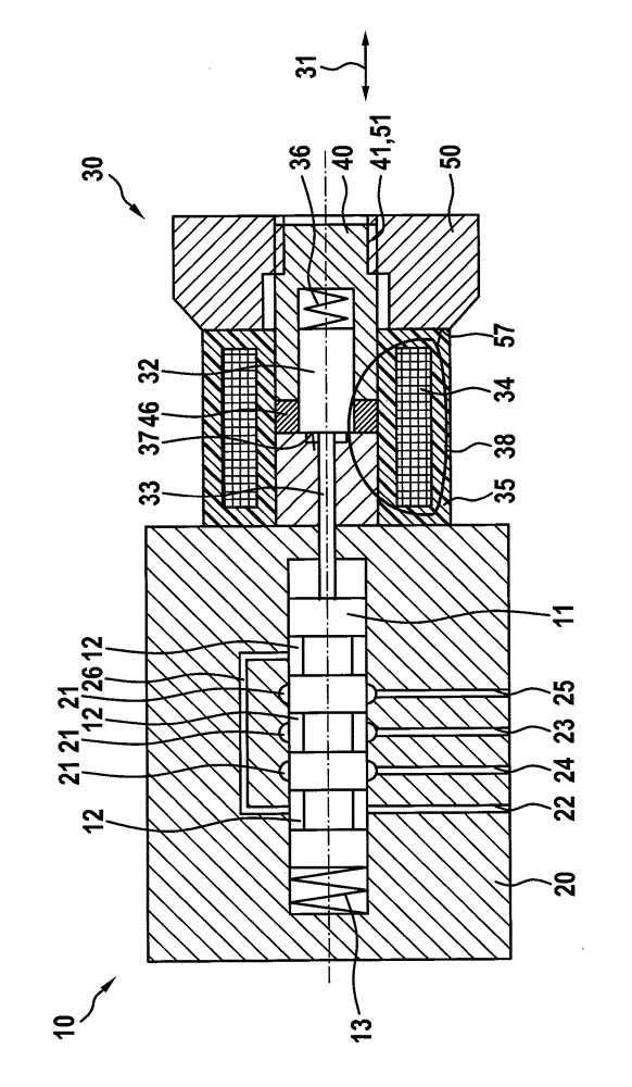
[0016] figure 1 A roughly schematic cross-section of a valve 10 with an actuating device 30 according to the invention is shown. The hydraulic valve 10 is shown by way of example as a slide valve, wherein the control body 11 is a control slide valve. However, the invention can also be used in seat valves. The valve 10 comprises a housing 20 , which is made, for example, of gray cast iron. The control body 11 is accommodated linearly displaceably with respect to the longitudinal direction 31 in a housing 20 which preferably consists of steel. The control body 11 is preferably designed with high precision in the form of a cylinder, wherein the control body is provided, for example, with three annularly encircling links 12 . In the housing 20 there is provided a cylindrical bore, preferably adapted with very little play to the control body 11 , which bore is provided with, for example, three annular housing grooves 21 . The link and the housing grooves 12 , 21 each define a c...


PUM


Abstract

An actuating device for a control body of a valve includes an armature guide configured to receive a magnetic armature and an armature plunger in such a manner that the magnetic armature and armature plunger can move in relation to a longitudinal direction. An outer thread is located on a longitudinal end of the armature guide that is remote from the armature plunger. The outer thread includes a first cross-sectional profile forming a thread tip that points towards an exterior. A holding nut having an inner thread is screwed onto the outer thread of the armature guide and lies at least indirectly on the synthetic material casing of the electrical coil. The inner thread includes a second cross-sectional profile that is complementary to the first cross-sectional profile, and a thread base configured in a clamping region in a gap free manner with respect to the first cross-sectional profile.

Description

technical field [0001] The invention relates to an actuation device according to the preamble of claim 1 . Background technique [0002] An actuating device for a control body of a hydraulic valve is known from DE 19952800 A1. The actuating device comprises a polar tube, in which an armature and an armature push rod are accommodated displaceably with respect to the longitudinal direction, the armature push rod protruding from the polar tube at the end facing away from the armature, so that the armature push rod there The end face can be in contact with the end face of the control body in the form of a control slide valve, so that the armature is movably coupled to the control body via the armature plunger. Around the polar tube there is an electrical coil, which is encased in a plastic casing. To produce the plastic housing, the coil is inserted into a mold, wherein the mold is then filled with a viscous plastic material, where it hardens. The plastic material surrounds t...

Claims


Application Information

Patent Timeline
Patent Type & Authority Applications(China)
IPC IPC(8): F16K31/06F16K11/07
CPCF16B39/284F16K31/0658F16K31/0675F16K27/048F16B39/30F16B1/00F16K31/0603F16K31/0613H02K1/148
Inventor C.德尔纳A.泽尔克L.蔡塞尔M.朗J.格吕恩
Owner ROBERT BOSCH GMBH
Why Eureka
Try Eureka