Three-point bending testing system based on dynamic fracture toughness of testing material

A technology of fracture toughness and three-point bending, which is applied in the field of three-point bending test system, can solve the problems of device system work flexibility discount, complex assembly, bulky overall structure, etc., to ensure self-mobility and adjustability, and ensure fixed point The effect of force resistance and great operational flexibility

Active Publication Date: 2014-10-01
HEFEI GENERAL MACHINERY RES INST
View PDF5 Cites 6 Cited by
  • Summary
  • Abstract
  • Description
  • Claims
  • Application Information

AI Technical Summary

Problems solved by technology

[0003] Although the overall operation process and concept of the current above-mentioned three-point bending experiment have been perfected, the physical experiment structure still has certain defects: in the above-mentioned system, each component is often set as figure 1 Although the fixed part shown in the figure plays a role in bearing a certain impact load and ensuring the working stability of the mechanism, on the one hand, the overall structure is bulky and the assembly is complicated, which is extremely unfavorable or even impossible for disassembly, replacement and maintenance operations, and is bulky Advanced testing systems not only often bring additional burdens for operations such as handling and maintenance, but also greatly reduce the working flexibility of the entire device system, and even need to redesign the test for different samples or different lengths of loading rods or impact rods system; on the other hand, there is no unified standardized design for the actual structure of the sample support device, and the size is often drawn up and adopted by each experimental department, which is also a major factor leading to different test results among various experimental departments. The actual operation of personnel brings great trouble

Method used


Image

  • Three-point bending testing system based on dynamic fracture toughness of testing material
  • Three-point bending testing system based on dynamic fracture toughness of testing material
  • Three-point bending testing system based on dynamic fracture toughness of testing material

Examples


Embodiment Construction

[0048] combine here Figure 2-19 Concrete structure and workflow of the present invention are described as follows:

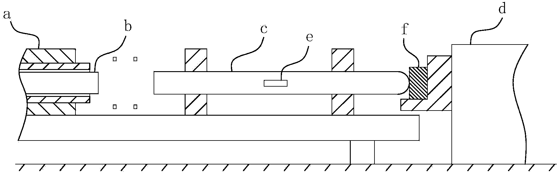
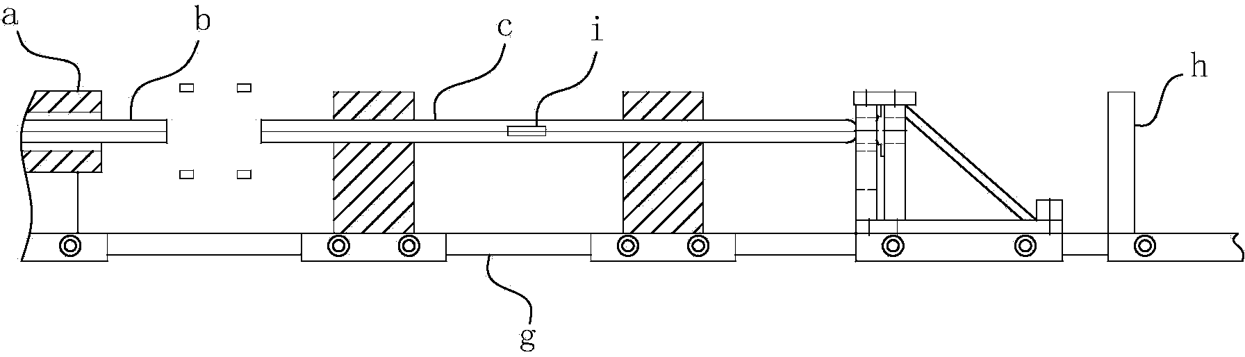
[0049] Concrete structure of the present invention, can refer to figure 2 As shown, it includes a base, on which a guide rail part g is arranged along the impact direction of the loading rod c, and on the guide rail part g, the air gun a, the striking rod b, the loading rod c, the supporting device and the baffle part h are arranged in sequence, wherein the striking rod b is arranged concentrically with the loading rod c, the support device is used to place and fix the test sample, the baffle part h is used to stop the loading rod c, the test system also includes an external information collection and processing device, and the information collection and processing device is equipped with an induction sheet i, the induction piece i is attached to the loading rod c. During the actual test, the compressed air gun a applies an instantaneous impulse to the impac...


PUM


Abstract

The invention belongs to the field of experimental equipment for the dynamic fracture toughness of a testing material and particularly relates to a three-point bending testing system based on the dynamic fracture toughness of the testing material. The system comprises a pedestal, wherein a support device, a loading rod, a knock rod, a compressed gas gun and a signal acquiring-processing device, a guide rail portion is arranged on the pedestal, and all the components are arranged on the guide rail portion and are fixedly connected and matched with the guide rail portion in a reciprocating guiding manner; the support device comprises a vertical plate which forms a matching portion matched with the guide rail portion, and grooves or through holes penetrating through a plate body are formed in the vertical plate; the support device further comprises a lining plate, and a through hole portion for being penetrated by the loading rod is arranged on the lining plate; lining units are further distributed on the lining plate; the supporting direction of the lining units, relative to a testing sample is opposite to the force applying direction of the loading rod. According to the system, the uniformity of acquired overall data can be guaranteed when the requirements of easiness in detaching and maintaining of a device are effectively realized.

Description

technical field [0001] The invention belongs to the field of experimental equipment for testing material dynamic fracture toughness, and in particular relates to a three-point bending test system based on testing material dynamic fracture toughness, which is used for high-efficiency evaluation and testing of the fracture resistance of metal material structures under impact loads ability. Background technique [0002] With the continuous development of social science and technology, the application of fracture mechanics in engineering has become quite common. In order to analyze the fracture of engineering structures, it is necessary to pass tests to obtain the fracture characteristic data of materials or structures, so that science can be better applied . The fracture test involves a wide range. According to the scale of the test, the fracture test can be divided into small laboratory tests, large laboratory tests and actual structural tests; according to the loading speed,...

Claims


Application Information

Patent Timeline
Patent Type & Authority Applications(China)
IPC IPC(8): G01N3/307G01N3/02
Inventor 陈学东潘建华胡时胜王冰艾志斌吕运容范志超
Owner HEFEI GENERAL MACHINERY RES INST
Why Eureka
Try Eureka