Laser rotation scanning lighting device and application thereof

A technology of rotating scanning and lighting devices, which is applied in the field of laser applications, can solve problems such as interference speckle and inhomogeneity of laser output light field, and achieve the effects of eliminating speckle and fringe, avoiding docking loss, and facilitating integration

Active Publication Date: 2014-10-01
Shandong Huaguang Optoelectronics Co. Ltd.
View PDF15 Cites 9 Cited by
  • Summary
  • Abstract
  • Description
  • Claims
  • Application Information

AI Technical Summary

Problems solved by technology

[0012] Aiming at the inhomogeneity of the laser output light field and the deficiency of interference

Method used


Image

  • Laser rotation scanning lighting device and application thereof
  • Laser rotation scanning lighting device and application thereof

Examples


Embodiment 1

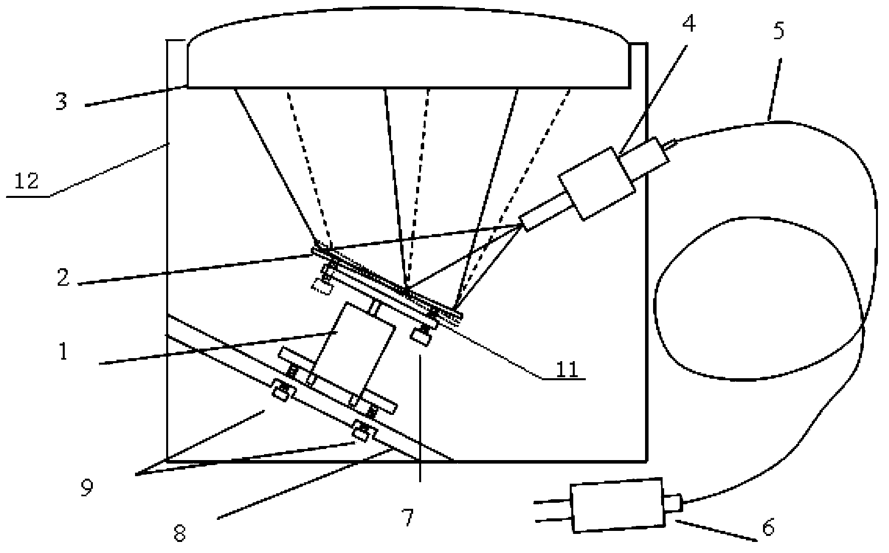
[0041] Such as figure 1 shown. A laser rotary scanning lighting device, comprising a rotating device that drives a reflector to rotate along the normal of the reflector, a reflector 2 and a laser light source; the laser light emitted by the laser light source is reflected by the reflector 2, and the reflected laser light As a scanning illumination source. The rotating device is a motor 1 rotating axially. The reflector 2 is a circular plane reflector coated with a high reflection film.

[0042] The laser light source is a fiber-coupled laser 6 , and the fiber-coupled laser 6 emits laser light on the surface of the mirror 2 through the optical fiber 5 and the output end 4 of the optical fiber.

[0043] The laser rotary scanning illuminating device further includes a housing 12 on which a light exit window 3 is arranged, and the scanning illumination light source is irradiated along the light exit window 3 . The housing 12 is cylindrical, and the light exit window 3 is arran...

Embodiment 2

[0045] Utilize the method for illuminating with laser rotary scanning lighting device as described in embodiment 1, comprise steps as follows:

[0046] (1) Adjust the placement angle of the motor 2: fix the motor 1 obliquely on the bottom plate 8, so that the angle range between the axial angle of the motor and the horizontal plane: 50°~75°;

[0047] (2) Adjust the placement angle of the reflector 2: fix an inclined plane reflector 2 on the rotor of the motor 1, and the angle range between the normal direction of the mirror surface and the motor shaft: 0°~15°;

[0048] (3) Adjust the position of the laser light source: the distance between the fiber output end 4 of the fiber-coupled laser 6 and the plane reflector 2: 10-40mm, and the angle between the laser output light and the normal direction of the reflector is 15°-40° Angle of , obliquely incident on the center of mirror 2;

[0049] (4) Turn on the power, and the laser light source is reflected by the rotating mirror 2 to...

Embodiment 3

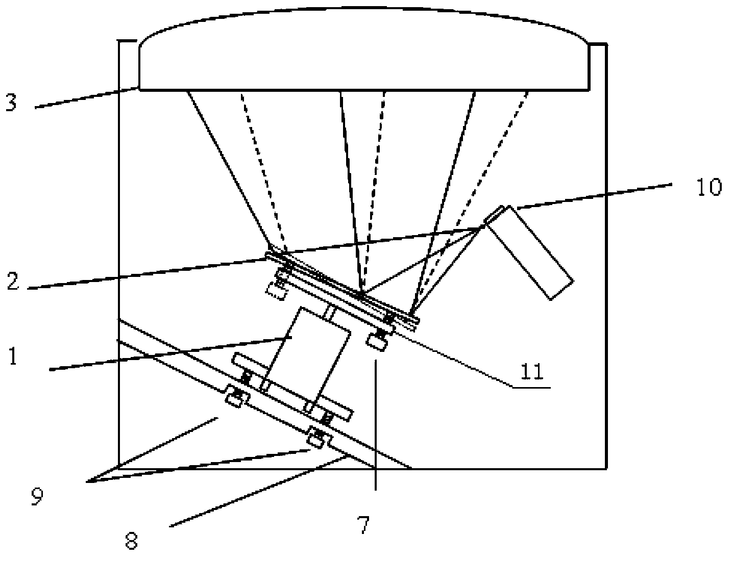
[0051] Such as figure 2 shown. A laser rotary scanning illumination device as described in Embodiment 1, the difference is that the laser light source is a semiconductor laser 10 .


PUM


Abstract

The invention discloses a laser rotation scanning lighting device. The laser rotation scanning lighting device comprises a rotating device used for driving a reflecting mirror to rotate along the normal line of the reflecting mirror, the reflecting mirror and a laser light source. The emergent laser light of the laser light source is reflected by the reflecting mirror, and the reflected laser light is used as a scanning lighting source. The invention further discloses a method using the laser rotation scanning lighting device for lighting. The laser light source can be scanned by rotating the reflecting mirror, a plurality of light spots can be overlapped rapidly on a final irradiation plane, the average effect is achieved visually, and the purpose for eliminating speckles and stripes can be achieved. The laser rotation scanning lighting device is simple in structure, low in cost, high in energy utilization rate, and particularly suitable for the application field of laser night vision, security and protection, laser projection and the like in which optical fiber output laser light is used as the light source.

Description

technical field [0001] The invention relates to a laser rotary scanning lighting device and its application, belonging to the technical field of laser application. Background technique [0002] Laser is a special light source with the characteristics of high brightness, good coherence and directivity. Due to this characteristic, laser has very important and wide applications in scientific research, engineering technology and industrial and agricultural production. Laser projection display and laser infrared night vision are two very important application fields that use laser as light source. [0003] Laser projection display uses laser as light source to replace the light source in traditional projection display system (such as high-pressure mercury lamp), which has the advantages of large color gamut, rich color, high color saturation and strong color expression, and can realize long-distance large-size The projection life can reach more than 20,000 hours. At present, the...

Claims


Application Information

Patent Timeline
IPC IPC(8): G02B26/10G02B27/48
Inventor 秦华兵乔世香于果蕾刘成成江建民
Owner Shandong Huaguang Optoelectronics Co. Ltd.
Why Eureka
Try Eureka