Double-sided packaging method of high-power laser bar and sintering fixture used for high-power laser bar packaging

A high-power laser and high-power technology, applied in the structural details of semiconductor lasers, lasers, laser components, etc., can solve the problems of exposed light-emitting surface of the bar, light blocking at the edge of the heat sink, etc., to achieve a wide range of applications, Solve the packaging problem and solve the effect of blocking the beam

Active Publication Date: 2014-10-01
Shandong Huaguang Optoelectronics Co. Ltd.
View PDF10 Cites 9 Cited by
  • Summary
  • Abstract
  • Description
  • Claims
  • Application Information

AI Technical Summary

Problems solved by technology

[0007] To sum up, in the packaging methods mentioned in the existing comparative patents, the heat dissipation of the chip is often focused on. However, due to the machining accuracy of the heat sink and the differences between different batches of chips, the conventional packaging method inevitably has the edge of the heat sink. The phenomenon of blocking light or the problem that the light-emitting surface of the bar is exposed

Method used


Image

  • Double-sided packaging method of high-power laser bar and sintering fixture used for high-power laser bar packaging
  • Double-sided packaging method of high-power laser bar and sintering fixture used for high-power laser bar packaging

Examples


Embodiment 1

[0033] Such as Figure 1-2 shown.

[0034] A method for double-sided packaging of a high-power laser bar, the method adopts a sintering fixture to package the high-power laser bar, and the method includes the following steps:

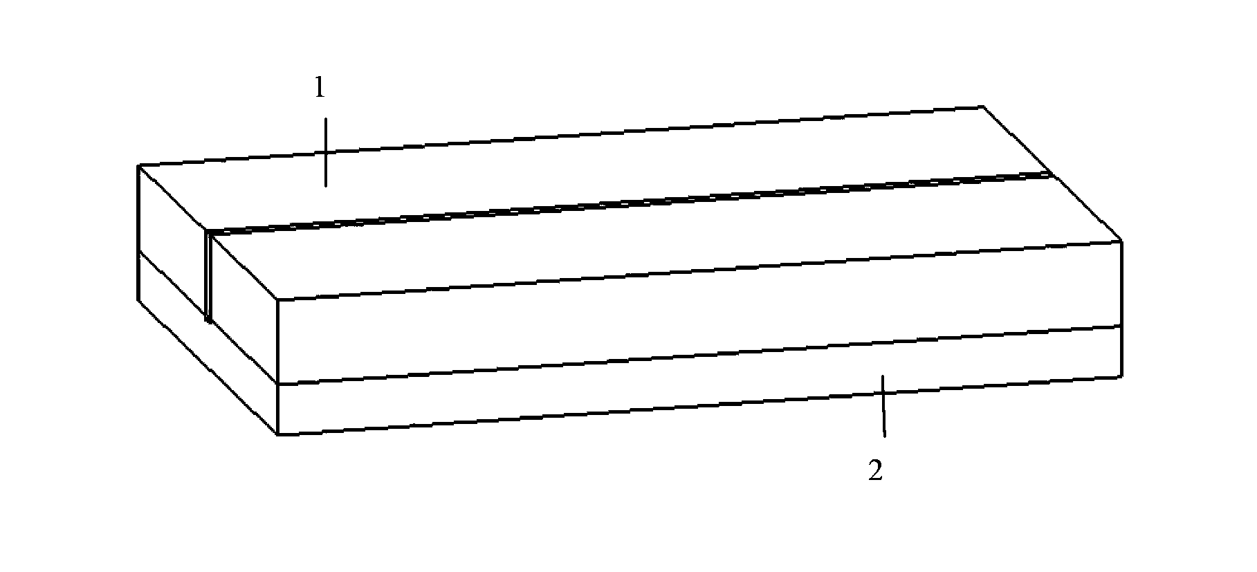
[0035] (1) Align the light-emitting surface of the high-power laser bar with the sides of the two first heat sinks 1 along the sintering fixture; the first heat sink is an oxygen-free copper heat sink, and the surface is plated with gold;

[0036] (2) welding one of the first heat sinks 1 to one side of the high-power laser bar, and welding the other first heat sink 1 to the other side of the high-power laser bar; During the welding process, the two first heat sinks 1 are aligned and clamped by a sintering jig.

[0037]Before the step (1), a high-power laser bar is installed on the insulating area of ​​the insulating ceramic substrate 2 according to the prior art; a patterned metal layer is provided on one side of the insulating ceramic substrate 2, a...

Embodiment 2

[0040] A method for double-sided packaging of high-power laser bars as described in Embodiment 1, the difference is that a metal layer is arranged on the other side of the insulating ceramic substrate 2, and a second metal layer is fixedly arranged on the metal layer. Heat sink. The second heat sink is an oxygen-free copper heat sink with a gold-plated surface.

Embodiment 3

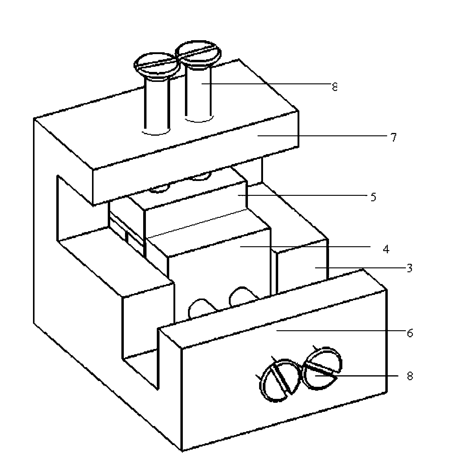
[0042] A sintering jig for the packaging method described in Embodiment 1, comprising a heating body 3, an upper baffle 7 fixedly arranged above the heating body 3, a front baffle 6 fixedly arranged in front of the heating body 3, an upper The backing plate 5 and the front backing plate 4, the upper backing plate 5 and the upper baffle plate 7 are arranged to move in parallel, and are used to fix the first heat sink and the insulating ceramic substrate, and the front backing plate 4 and the The front baffle 6 is arranged to move in parallel, and is used to fix the high-power laser bar and the first heat sink.

[0043] The upper backing plate 5 is arranged parallel to the upper baffle plate 7 through fixing screws 8 . The front backing plate 4 is arranged parallel to the front baffle plate 6 through the fixing screws 8 . The heating body 3, the upper baffle 7 and the front baffle 6 of the sintering fixture are all made of oxygen-free copper. Both the front backing plate 4 and...


PUM


Abstract

The invention relates to a double-sided packaging method of a high-power laser bar. The method comprises the following steps that (1) the end face of the light-emitting surface of the high-power laser bar is made to be flush with the end faces of the side faces of two first heat sinks through punching along a sintering fixture; (2) one of the first heat sinks is welded onto one side face of the high-power laser bar, and the other first heat sink is welded onto the other side face of the high-power laser bar; in the welding process, the sintering fixture is used for making the two first heat sinks to be flush with each other and clamping the two first heat sinks. According to the double-sided packaging method of the high-power laser bar, the light-emitting surface of the high-power laser bar is perpendicular to the sintering fixture and is tightly attached to a heating body of the sintering fixture downwards, therefore, the light-emitting surface of the high-power laser bar is completely flush with the edges of the first heat sinks, and the smile phenomenon caused due to the fact that thermal stress is not well processed is effectively avoided. The packaging method can be used for horizontal GS stacks and can also be used for vertical arrays, and the application range is relatively wide.

Description

technical field [0001] The invention relates to a double-sided encapsulation method of a high-power laser bar and a sintering jig for encapsulation thereof, belonging to the technical field of semiconductor laser encapsulation. Background technique [0002] Due to the advantages of small size, light weight, high photoelectric conversion efficiency, long service life and easy adjustment, semiconductor lasers are widely used in industry, medical treatment, communication, information display, military and other fields. The research and development level of high-power semiconductor lasers has affected the development level of national defense technology and industry. Its application can mainly be used in the guidance and tracking of missiles, weapon simulation and bomb detonation, night vision radar monitoring and so on. The application of high-power bar laser can also be used in industrial metal cutting and engraving, metal melting and coating reprocessing. In the medical fiel...

Claims


Application Information

Patent Timeline
Patent Type & Authority Applications(China)
IPC IPC(8): H01S5/02H01S5/022H01S5/024
Inventor 张骋王娜李沛旭汤庆敏
Owner Shandong Huaguang Optoelectronics Co. Ltd.
Why Eureka
Try Eureka