Digital control system and control method of three-phase three-level pfc circuit

A digital control system and digital control technology, applied in the direction of high-efficiency power electronic conversion, electrical components, output power conversion devices, etc., can solve the problems of increasing device complexity, difficulty, and complex algorithms, and simplify the calculation of turn-on time , less sampling data, and simple algorithm

Inactive Publication Date: 2016-07-13
GUANGDONG UNIV OF TECH
View PDF2 Cites 0 Cited by
  • Summary
  • Abstract
  • Description
  • Claims
  • Application Information

AI Technical Summary

Problems solved by technology

[0003] At present, there are many methods for the control of three-level PFC circuits. Chinese patents 200910145279.1 and 200710080000.7 both provide a space vector control method, and 200910128568.0 provides a method for optimizing switching operations to ensure that the phase of the current is consistent with the voltage; domestic journals Some people also provide one-cycle (One-Cycle) control methods in the literature; these control methods have their own characteristics. Vector control is a control method based on digital chips, which can be flexibly applied in practice and is suitable for high-power applications. However, its algorithm is relatively complicated, and it needs to sample the input voltage, input current, output voltage and current of the three phases, which increases the complexity of the device; the method of single-cycle control is relatively simple, no need to sample the input voltage, only need to Current and output voltage are sampled, but because real-time input current is required to participate in the comparison to obtain the control amount, it is difficult to use digital chips to achieve single-cycle control

Method used


Image

  • Digital control system and control method of three-phase three-level pfc circuit
  • Digital control system and control method of three-phase three-level pfc circuit
  • Digital control system and control method of three-phase three-level pfc circuit

Examples


Embodiment 1

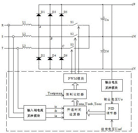
[0039] One of the implementation modes of the digital control system and the control method of a kind of three-phase three-level PFC circuit of the present invention, such as figure 1 As shown, the digital control system of the three-phase three-level PFC circuit includes:

[0040] The input phase current sampling module is used to sample the input phase currents ia, ib, and ic every set time Tk; ia, ib, and ic are respectively R-phase input current, S-phase input current, and T-phase input current;

[0041] The output voltage sampling module is used for sampling the output voltage Uo;

[0042] The PID regulator is used to adjust the output voltage Uo to a stable voltage control value Uc according to the given voltage Uref every set time Tc;

[0043] The on-time calculator is used to calculate the input phase current ia, ib, ic and the voltage control value Uc every set time Tk to obtain the on-time Tona, Tonb, Tonc of the switches S1, S2, and S3;

[0044] The limit comparat...

Embodiment 2

[0064] One of the implementation modes of the digital control system and the control method of a kind of three-phase three-level PFC circuit of the present invention, such as Figure 1 to Figure 3 As shown, the main technical solutions of this embodiment are basically the same as those of Embodiment 1, and the features not explained in this embodiment are explained in Embodiment 1, and will not be repeated here. The difference between this embodiment and embodiment 1 is:

[0065] The time interval Tc for obtaining the voltage control value Uc is greater than or equal to 10 times the switching period Ts.

[0066] And the relationship between Tk and switching period Ts is: when the switching period Ts is less than 10us, Tk takes 5 times the switching period Ts; when the switching period Ts is greater than or equal to 10us and less than 20us, Tk takes 3 times the switching period Ts; when Ts is greater than or equal to At 20us, Tk takes twice the switching period Ts.

[0067] ...


PUM


Abstract

The present invention relates to the technical field of digital control of power electronic circuits, in particular to a digital control system and control method of a three-phase three-level PFC circuit. The digital control system includes an input phase current sampling module, an output voltage sampling module, and a PID regulator. Turn-on time calculator, PWM module; the turn-on time calculator calculates the input phase current ia, ib, ic and the output voltage Uo adjusted by the PID regulator to obtain the turn-on time of the switch, and limit the comparator to obtain the corresponding turn-on time change The PWM module updates the comparator value of the PWM module according to the change value of the turn-on time that limits the output of the comparator, and controls the corresponding switching tubes of each phase. The digital control system and control method only need to sample the three-phase input current and output voltage, the calculation of the control quantity is simple and time-saving, the unit power factor of the circuit is realized, and the harmonic pollution is small.

Description

technical field [0001] The invention relates to the technical field of digital control of power electronic circuits, in particular to a digital control system and a control method of a three-phase three-level PFC circuit. Background technique [0002] Three-phase three-level power factor correction (PFC) circuit topology such as figure 1 As shown in the upper part, where R, S, and T are three-phase AC voltage inputs, each phase input is respectively connected to inductors L1, L2, and L3, and the other ends of the inductors are respectively connected to diodes D1, D2, D3, D4, D5, and D6. The midpoints A, B, and C of the bridge circuit, and the N poles of the diodes D1, D3, and D5 are commonly connected to the output capacitor C u The positive pole is the positive pole output P of the circuit, and the P poles of diodes D2, D4, and D6 are commonly connected to the output capacitor C d The negative pole is the negative pole output N of the circuit, and S1, S2, and S3 are three...

Claims


Application Information

Patent Timeline
Patent Type & Authority Patents(China)
IPC IPC(8): H02M1/42
CPCY02B70/10
Inventor 周映虹黄熙陈小琴梁昌宇
Owner GUANGDONG UNIV OF TECH
Why Eureka
Try Eureka