Three-phase sensored bldc motor drive system and its drive method
A technology of driving system and driving method, which is applied in the direction of electronic commutator, etc., can solve problems such as the failure of the driving system to work normally, and achieve the effects of overcoming the failure of the system to drive normally, convenient production and application, and a wide range of applications
- Summary
- Abstract
- Description
- Claims
- Application Information
AI Technical Summary
Problems solved by technology
Method used
Image
Examples
Embodiment 1
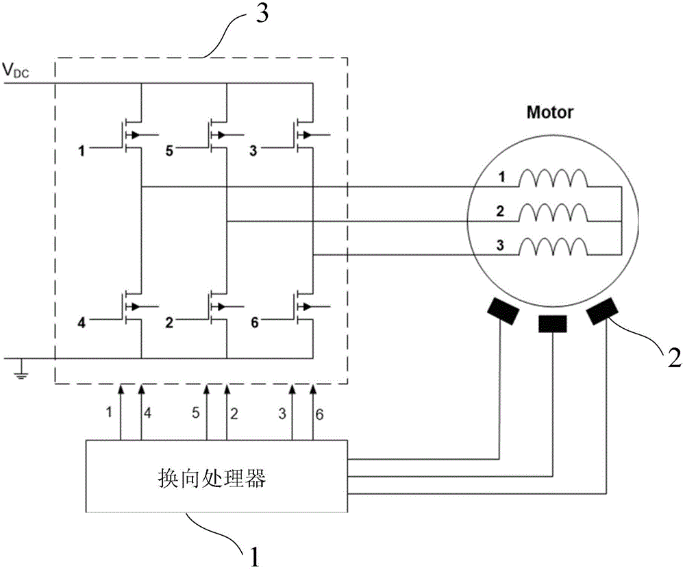
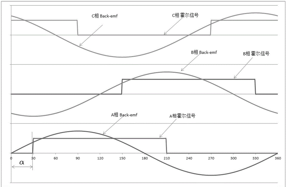
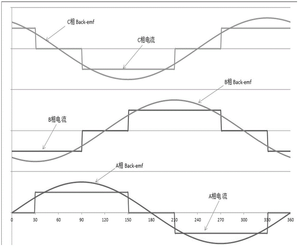
[0054] Figure 1~3 As shown, the system of the present invention is composed of a commutation processor 1 , three Hall sensors 2 with the same structure, and a three-phase drive circuit 3 . Among them, the three Hall sensors 2 are all arranged near the rotor magnetic steel of the three-phase BLDC motor; the three-phase drive circuit 3 is composed of three groups of field effect transistors with the same structure, and each group of field effect transistors is composed of two It is composed of two field effect transistors connected in series, and the connection point between the two field effect transistors in each group of field effect transistors is connected to one phase winding of the three-phase windings of the three-phase BLDC motor, that is, these three The three connection points in the field effect transistor group respectively correspond to a phase winding. When in use, the rotor position signals detected by the three Hall sensors 2 are processed by the commutation p...
Embodiment 2
[0058] Such as Figure 4 As shown, this embodiment is based on Embodiment 1, and the driving implementation method when any Hall sensor fails, and the specific steps are as follows:
[0059] (1) The drive system detects whether there is a damaged Hall sensor, and if there is, the problematic Hall sensor is shielded; if not, it is driven according to the normal driving method with a Hall sensor;
[0060] (2) Generate the motor rotor current according to the TH-1 starting method, and keep the current until the Hall sensor generates a new state change signal;
[0061] (3) Determine whether the new state change signal is the first state change signal; if yes, then return to step (2); no, then perform step (4);
[0062] (4) Calculate the time interval Δt of the previous two new state change signals;
[0063] (5) Determine whether the damaged Hall sensor should logically generate a state change signal within the past Δt, if yes, then generate a new current switching signal accordi...
Embodiment 3
[0083] Such as Figure 6 As shown, the difference between this embodiment and embodiment 2 is that embodiment 1 is a start-up method when one Hall sensor fails, and this embodiment is when two Hall sensors fail at the same time. The start method, the specific steps are as follows:
[0084] (1) The drive system specifies and shields the Hall sensor in question;
[0085] (2) Generate the motor rotor current according to the TH-2 starting method, and keep the current until the Hall sensor generates a new state change signal;
[0086] (3) Determine whether the new state change signal is the first state change signal; if yes, then return to step (2); no, then perform step (4);
[0087] (4) Generate a new current switching signal according to the current current distribution state and the signal processing logic under normal conditions;
[0088] (5) Calculate the time interval Δt of the previous two new state change signals, and use the Δt / 3s second time value to update the 60° t...
PUM
 Abstract
Description
Claims
Application Information
 - R&D
- Intellectual Property
- Life Sciences
- Materials
- Tech Scout
- Unparalleled Data Quality
- Higher Quality Content
- 60% Fewer Hallucinations
Browse by: Latest US Patents, China's latest patents, Technical Efficacy Thesaurus, Application Domain, Technology Topic, Popular Technical Reports.
© 2025 PatSnap. All rights reserved.Legal|Privacy policy|Modern Slavery Act Transparency Statement|Sitemap|About US| Contact US: help@patsnap.com


