Power supply control device

A power control device and power control technology, applied in the direction of motor control, emergency protection circuit device, control system, etc., can solve problems such as high voltage abnormality, and achieve the effect of cost reduction and reliable stop

Inactive Publication Date: 2014-10-01
DAIKIN IND LTD
View PDF4 Cites 5 Cited by
  • Summary
  • Abstract
  • Description
  • Claims
  • Application Information

AI Technical Summary

Problems solved by technology

[0003] However, in the compressor, there are cases where, for example, abnormal high pressure occurs

Method used


Image

  • Power supply control device
  • Power supply control device
  • Power supply control device

Examples


Embodiment Construction

[0031] Hereinafter, the power supply control device of the present invention will be described in detail with reference to the drawings. The following embodiments are specific examples of the present invention and do not limit the technical scope of the present invention.

[0032] (1) Overall structure

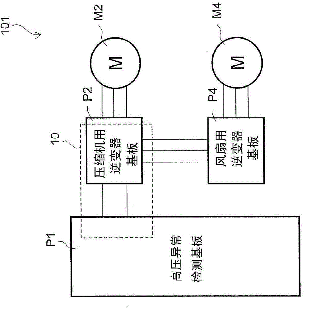
[0033] figure 1 is a schematic structural diagram of the motor drive system 101 . The motor drive system 101 includes a plurality of motors M2, M4, ..., a high-voltage abnormality detection board P1 on which some components of the power control device 10 according to this embodiment are mounted, and a compressor for a compressor on which the remaining components of the power control device 10 are mounted. The inverter substrate P2 and the fan inverter substrate P4 are configured.

[0034] The motors M2, M4, . . . are respectively a drive source for a compressor of an outdoor unit of an air conditioner, which is an example of a refrigeration unit, and a drive source for a fa...


PUM


Abstract

The purpose of the invention is to provide a power supply control device that reliably stops the operation of a compressor when an abnormality occurs in the compressor. A compressor inverter (28) has a plurality of transistors (Q28a to Q28f) and turns on or off the transistors (Q28a to Q28f) to generate driving voltages (SU1 to SW1) for driving a compressor motor (M2) and output the driving voltages (SU1 to SW1) to the compressor motor (M2). A compressor microcomputer (30) controls the compressor inverter (28). A switching power supply unit (24) generates a first power supply (V1) supplied to the compressor microcomputer (30). When an abnormality occurs in a compressor, a power supply control switch (S25) stops the switching power supply unit (24) from generating the first power supply (V1), thereby stopping the control by the compressor microcomputer (30).

Description

technical field [0001] The present invention relates to a power control device. Background technique [0002] A refrigeration device such as an air conditioner is equipped with various devices such as a compressor and a fan. As a drive source for each of the above devices, a motor is often used. The motor is driven by electric power supplied from a commercial power supply unit (hereinafter simply referred to as a power supply). [0003] However, in the compressor, for example, a high pressure abnormality may occur. Abnormal high pressure refers to a phenomenon in which the pressure of the refrigerant compressed by the compressor deviates from the normal pressure range due to some reason related to the compressor, and is in a high pressure state higher than a predetermined value on the high pressure side of the range. [0004] On the other hand, as disclosed in Patent Document 1 (Japanese Patent No. 4738129), there is known a technique of cutting off power supply to a moto...

Claims


Application Information

Patent Timeline
Patent Type & Authority Applications(China)
IPC IPC(8): H02P29/02
CPCH02M1/36H02H7/0833H02M7/44H02P29/02H02M7/5387Y10S388/903
Inventor 中下裕子八木达
Owner DAIKIN IND LTD
Why Eureka
Try Eureka