Combined automatic feeding machine tool

An automatic feeding and combined technology, applied in milling machines, milling machine equipment, metal processing, etc., can solve the problems of non-removable hoppers, cumbersome disassembly and maintenance, and difficulty in automatic loading and unloading of materials, so as to facilitate replacement and realize industrialized continuous production. Effect

Active Publication Date: 2014-10-08
南通新棉锦纺织品有限公司
View PDF6 Cites 1 Cited by
  • Summary
  • Abstract
  • Description
  • Claims
  • Application Information

AI Technical Summary

Problems solved by technology

Since the hopper of this kind of automatic feeding device cannot be disassembled, and there is only a single hopper, when the hopper is deformed due to bumping, it is easy to jam the main workpiece, and the disassembly and maintenance are more cumbersome; in addition, it is difficult to realize industrialized automatic loading and unloading of materials with this single fixed hopper

Method used


Image

  • Combined automatic feeding machine tool
  • Combined automatic feeding machine tool
  • Combined automatic feeding machine tool

Examples


Embodiment 1)

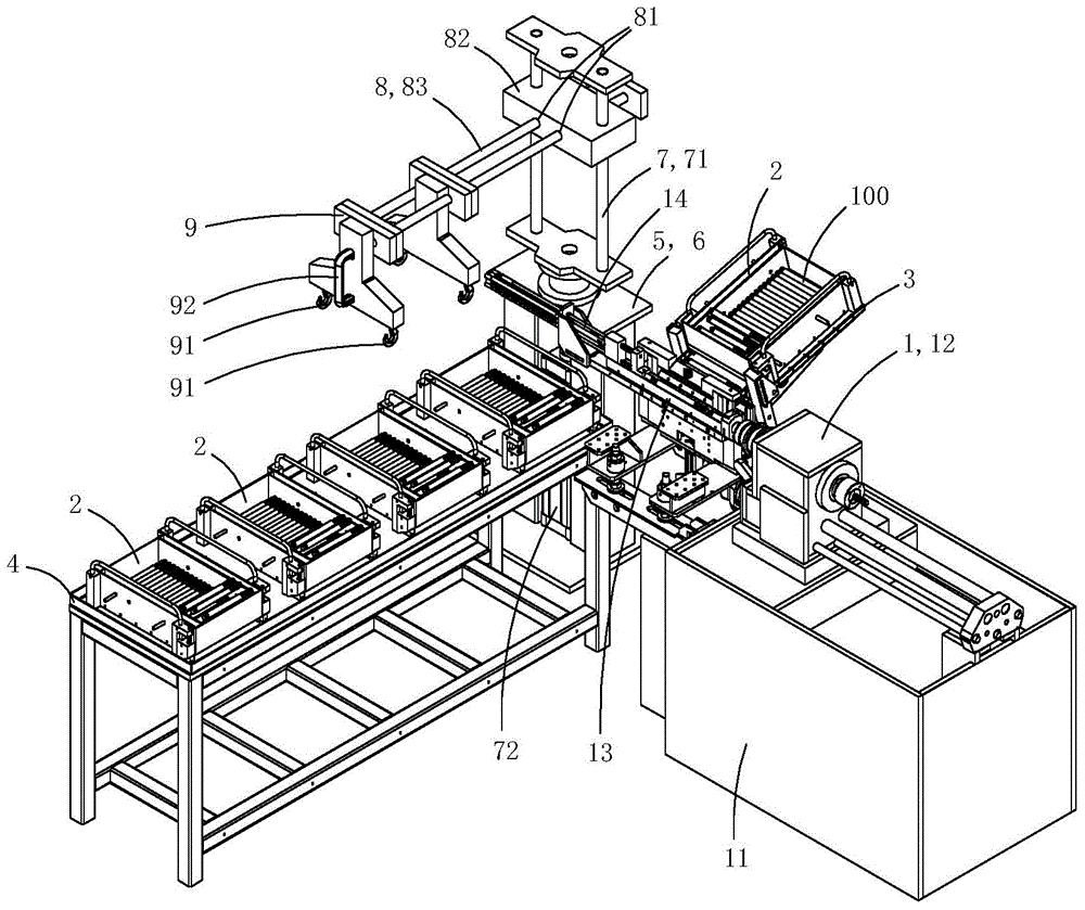
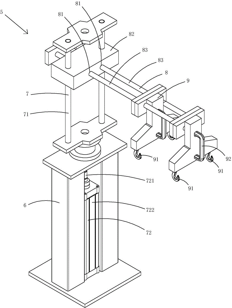
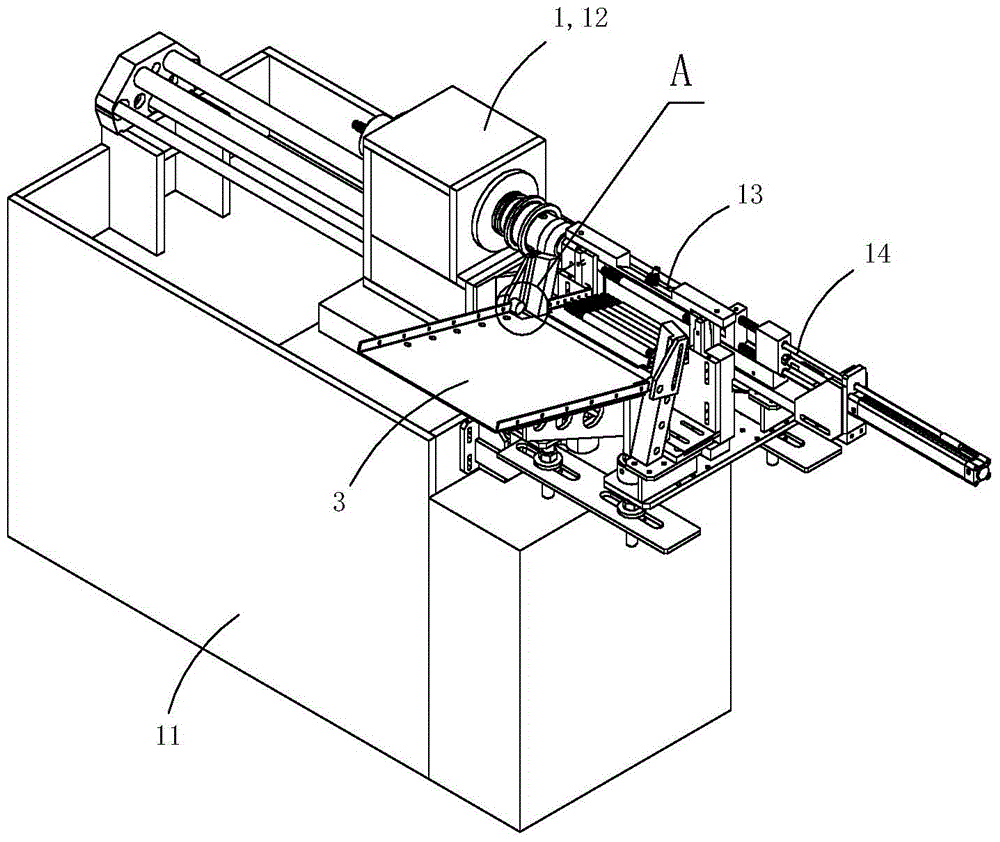
[0016] Figure 1 to Figure 8 A specific embodiment of the invention is shown in which, figure 1 It is a schematic diagram of a three-dimensional structure of the present invention; figure 2 for figure 1 A schematic diagram of a three-dimensional structure of the feeding device in the machine tool shown; image 3 for figure 1 A schematic diagram of the three-dimensional structure of the machine tool shown after removing the feeding device, unloading rack and hopper; Figure 4 for image 3 Partial enlarged schematic diagram of A; Figure 5 for figure 1 A schematic diagram of a three-dimensional structure of the hopper in the machine tool shown; Figure 6 for Figure 5 A top view of the hopper shown; Figure 7 for Figure 5 A schematic cross-sectional structure of the hopper shown; Figure 8 for Figure 7 A schematic diagram of the structure of the shown hopper resting on the hopper support.

[0017] Present embodiment is a kind of combined automatic feeding machine...


PUM


Abstract

The invention discloses a combined automatic feeding machine tool comprising a machine tool body, hoppers, a hopper support arranged on the machine tool body, a material placement frame and a feeding device used for transferring the hoppers on the material placement frame to the hopper support. The feeding device comprises a feeding support, a lifting mechanism arranged on the feeding support in a rotating mode, a horizontally moving mechanism carrying out reciprocating motion in the horizontal direction, and a hooking mechanism used for hooking the hanging-connecting portion of each hopper. The lifting mechanism comprises lifting rods and a drive mechanism driving the lifting rods to move vertically, and the lifting rods are arranged on the feeding support in a rotating mode. The horizontally moving mechanism comprises a locating board and sliding rods, the locating board is provided with horizontal sliding holes and is arranged on the lifting rods, and the sliding rods can carry out reciprocating motion along the horizontal sliding holes. The hooking mechanism comprises hooks arranged on the sliding rods. As the feeding device used for transferring the hoppers on the material placement frame to the hopper support is arranged, the hoppers are replaced conveniently, and continuous industrial production is achieved easily.

Description

technical field [0001] The invention belongs to the technical field of machine tool structure design, and in particular relates to a combined automatic feeding machine tool. Background technique [0002] In existing machine tools, its automatic feeding device generally includes a hopper fixedly arranged on the machine tool body. The hopper has a fixed discharge port. During work, the workpieces in the hopper fall from the discharge port to preset positions in sequence, so that each workpiece For processing. Since the hopper of this kind of automatic feeding device cannot be disassembled, and there is only a single hopper, when the hopper is deformed due to bumping, it is easy to get stuck in the main workpiece, and disassembly and maintenance are more cumbersome; in addition, it is difficult to realize industrial automatic loading and unloading of materials with this single fixed hopper. Contents of the invention [0003] The purpose of the present invention is to provide...

Claims


Application Information

Patent Timeline
Patent Type & Authority Applications(China)
IPC IPC(8): B23Q7/10
CPCB23C1/02B23Q7/00B23Q7/005B23Q7/06B23Q7/10B23Q7/106B23Q7/1415B23Q7/1494H04N1/00519H04N1/00557H04N1/00559H04N1/04
Inventor 申俊
Owner 南通新棉锦纺织品有限公司
Why Eureka
Try Eureka