
A clamping fixture for a rail vehicle traction rod

A technology for pulling rods and rail vehicles, which is applied in the field of clamping fixtures, can solve the problems of inflexibility and monotonous tooling structure, and achieve the effects of reducing alignment work, simple structure, and convenient clamping work

Active Publication Date: 2016-03-09
CHUANLI ELECTRIC CO LTD
View PDF10 Cites 0 Cited by
  • Summary
  • Abstract
  • Description
  • Claims
  • Application Information

AI Technical Summary

Problems solved by technology

[0002] In the processing of traction rods today, since the models of various traction rods are different, there are great requirements for the clamping tooling. However, the existing tooling structure is relatively monotonous and cannot be flexibly adapted. In today's rapidly developing industry, it is very necessary to design a pressing device that can be positioned quickly and can be applied to any kind of pulling rod

Method used


Image

  • A clamping fixture for a rail vehicle traction rod
  • A clamping fixture for a rail vehicle traction rod
  • A clamping fixture for a rail vehicle traction rod

Examples


Embodiment Construction

[0014] Below in conjunction with accompanying drawing and specific embodiment, further clarifies the present invention, and this practical example is carried out under the premise of the technical solution of the present invention, understands that these embodiments are only for illustrating the present invention and are not intended to limit the scope of the present invention.

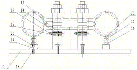
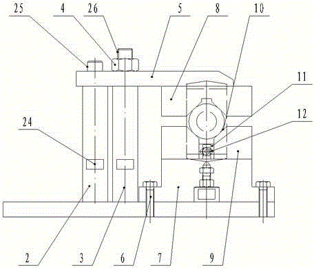
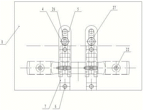
[0015] Such as Figure 1 to Figure 3 As shown, a compression fixture for rail vehicle traction rods includes a compression device, a movable compression device and a support device; the compression device is provided with a bottom plate 1, a support rod 2, a compression rod 3, a lock Tighten the nut 4 and the pressure plate 5, the top of the base plate 1 is provided with a support rod 2 and a compression rod 3, the support rod 2 and the compression rod 3 are connected to the base plate 1 through threads, a polished rod 25 is arranged above the support rod 2, and a light rod 25 is arranged above the com...


PUM


Abstract

The invention discloses a pressing fixture for a traction rod of a rail vehicle, which comprises a pressing device, a movable pressing device and a supporting device; a bottom plate, a supporting rod, a pressing rod, a locknut and a pressing plate are arranged on the pressing device; an upper V-shaped block, a lower V-shaped block, a lower supporting seat, a fixed bolt, a second locknut and an outer hexagon bolt are arranged on the movable pressing device; a supporting nut, a third locknut and a supporting bolt are arranged on the supporting device. The pressing fixture has the benefit that the structure is simple, the operation is convenient and practical, and the pressing fixture can be suitable for pressing any traction rod, has larger pressing force and can be automatically aligned through a step shaft and a first light hole, so that great convenience is brought to the pressing work, and much unnecessary alignment work in the previous work is greatly reduced.

Description

technical field [0001] The invention relates to a clamp, in particular to a pressing clamp for a traction rod of a rail vehicle. Background technique [0002] In the processing of traction rods today, since the models of various traction rods are different, there are great requirements for the clamping tooling. However, the existing tooling structure is relatively monotonous and cannot be flexibly adapted. In today's rapidly developing industry, it is very necessary to design a pressing device that can be positioned quickly and that can be applied to any kind of pulling rod. Contents of the invention [0003] The object of the present invention is to provide a clamping fixture for a traction rod of a rail vehicle in view of the deficiencies in the prior art. [0004] In order to achieve the above object, the method adopted in the present invention is: a compression fixture for rail vehicle traction rods, comprising a compression device, a movable compression device and a ...

Claims


Application Information

Patent Timeline
Patent Type & Authority Patents(China)
IPC IPC(8): B25B11/00
CPCB25B11/00
Inventor 邹云平何保平孙柳青
Owner CHUANLI ELECTRIC CO LTD
Learn More