
HUD

A head-up display device and optical-mechanical technology, applied in optical observation devices, transportation and packaging, optics, etc., can solve problems such as unsuitable aftermarket, eye fatigue, and reduced driving safety, so as to reduce distraction Opportunity, small size and space occupation, and the effect of improving driving safety

Active Publication Date: 2016-05-04
JIANGXI PYROGARD TECH CO LTD
View PDF7 Cites 0 Cited by
  • Summary
  • Abstract
  • Description
  • Claims
  • Application Information

AI Technical Summary

Problems solved by technology

[0003] The existing head-up display device has the following problems: In order to meet the requirements of displaying complex and colorful driving information, a larger optical refraction device is required, so the space requirement for the front cab of the vehicle is relatively high, and in order to adapt to the interior of the vehicle Due to the limited space, only joint manufacturers can accommodate the equipment for projecting driving information images in the instrument panel of the vehicle, which requires modification of the original structure of the vehicle, which is not suitable for the aftermarket; directly presenting the driving information images on the windshield On the glass, the distance between the driving information image and the human eye is relatively close. As we all know, the lens of the human eye will automatically adjust the focal length of the lens according to the distance of the object under normal use. If the information image is presented on the windshield, or the distance between the human eye and the human eye is relatively short, in order to clearly view the external target and the image provided by the head-up display device at the same time during driving, the driver's eyeballs need to repeat Adjusting the focus will easily cause eye fatigue and discomfort, and reduce driving safety. According to relevant research, it takes about 0.8 seconds for the human eye lens to move from far to near, and it is easy to cause irreversible traffic during this time. Hidden danger

Method used


Image

  • HUD
  • HUD
  • HUD

Examples


Embodiment Construction

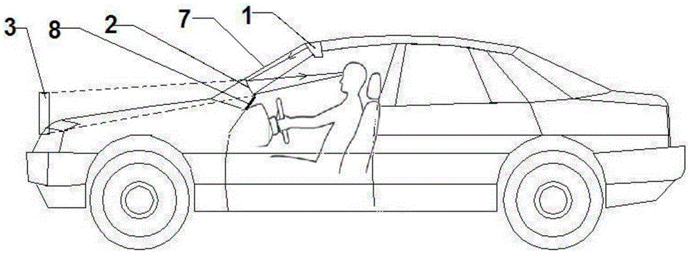
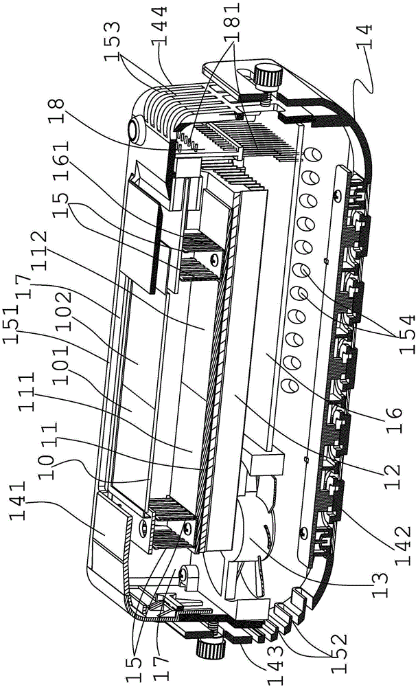
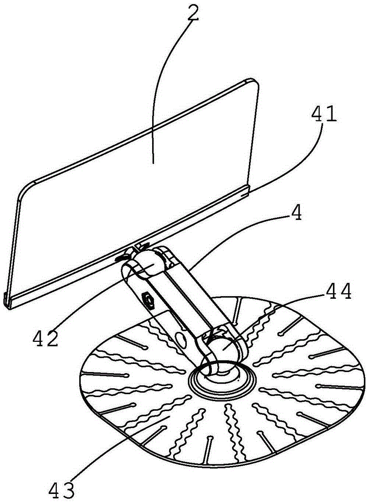
[0033] Such as Figure 1 to Figure 5 The shown head-up display device includes: an optical machine 1 installed on the upper end of the front windshield 7, the optical machine 1 includes a liquid crystal panel 10 for displaying images and a backlight 11 placed behind the liquid crystal panel 10 and the coated spherical lens 2 placed in front of the driver and placed on the instrument panel 8, the coated spherical lens 2 is used to receive the image light projected by the optical machine 1, and convert the optical path of the image light to form The corresponding enlarged virtual image 3; the optical path length between the coated spherical lens 2 and the optical machine 1 is less than the focal length of the coated spherical lens 2; the driver can see the magnified through the coated spherical lens 2 Virtual image 3; further, the coated spherical lens 2 includes a spherical lens, and an anti-reflection coating and a high-reflective coating arranged on the surface of the spheric...


PUM


Abstract

The invention discloses a head-up display device, comprising: an optical machine installed on the upper end of the front windshield, the optical machine includes a liquid crystal panel for displaying images and a backlight placed behind the liquid crystal panel; A coated spherical lens placed in front of the instrument panel, the coated spherical lens is used to receive the image light projected by the optical machine, and convert the optical path of the image light to form a corresponding enlarged virtual image; the driver The magnified virtual image can be seen through the coated spherical lens; the optical path length between the coated spherical lens and the optical machine is shorter than the focal length of the coated spherical lens. The installation of the head-up display device of the present invention does not need to change the original structure of the vehicle, fully utilizes the limited space in the front cockpit of the vehicle such as a car, and has a compact structure, small volume and small occupied space.

Description

technical field [0001] The invention relates to a head-up display device. Background technique [0002] The head-up display device is an electronic display device commonly used in the field of vehicles. It is used to display various driving information such as driving speed and fuel level on the windshield of the vehicle viewed by the driver, so as to prevent the driver from alternately observing external targets and The visual operation changes caused by the internal instruments can prevent eye fatigue and improve driving safety. [0003] The existing head-up display device has the following problems: in order to meet the requirements of displaying complex and colorful driving information, a larger optical refraction device is required, so the space requirement for the front cab of the vehicle is relatively high, and in order to adapt to the interior of the vehicle Due to the limited space, only joint manufacturers can accommodate the equipment for projecting driving infor...

Claims


Application Information

Patent Timeline
Patent Type & Authority Patents(China)
IPC IPC(8): B60R1/00G02B27/01
Inventor 徐洪
Owner JIANGXI PYROGARD TECH CO LTD
Learn More