

Spinning device and method for melt-spun spandex
A technology for spandex spinning and production equipment, which is applied in melt spinning, textile and papermaking, filament/thread forming, etc. It can solve the problems of inconvenient replacement of components, high energy consumption, and large space occupation, and achieve increased operability Space, reduce heat dissipation area, reduce the effect of box volume
- Summary
- Abstract
- Description
- Claims
- Application Information
AI Technical Summary
Problems solved by technology
Method used
Image

Examples
Embodiment 2
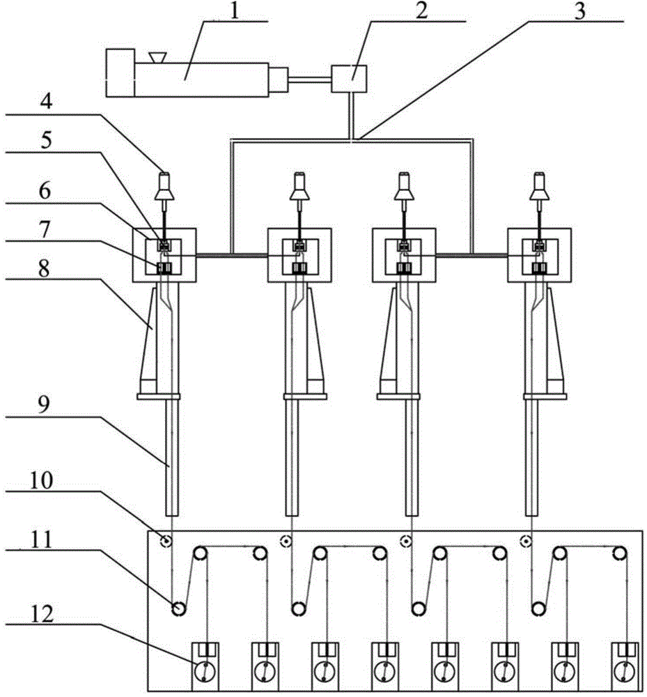
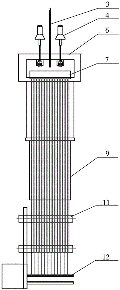
[0032] A melt-spinning spandex spinning production equipment provided in an embodiment of the present invention includes a screw extruder 1, a cross-linking reaction system, a metering pump system, a spinning box 6, a spandex spinning assembly 7, a side blowing system 8, and a tunnel 9. Oiling system 10, spandex winding head 12;
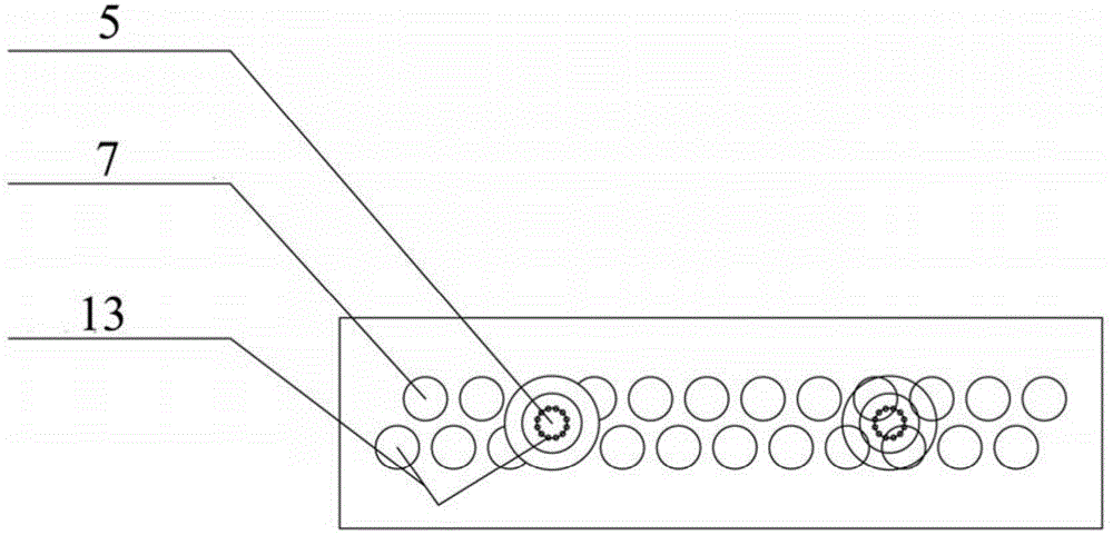
[0033] The screw extruder 1 is connected to the cross-linking reaction system, the cross-linking reaction system includes a cross-linking reaction device 2 and a melt pipeline 3, the screw extruder 1 is connected to the cross-linking reaction device 2, and the cross-linking reaction device 2 passes through the melt The pipeline 3 is connected to the metering pump system. The metering pump system includes the metering pump 5 and the metering pump transmission device 4 connected thereto. The metering pump is connected to the spandex spinning assembly 7 through the branch pipe 13, and the spandex spinning assembly 7 is arranged in the spinning box 6. , ...
Embodiment 3
[0036] A method for producing melt-spun spandex spinning, comprising the steps of:
[0037] The spandex slices are fed into the screw extruder 1 through the hopper, and after being melted by the screw extruder 1, the spandex melt is extruded into the crosslinking reaction device 2;
[0038] After the spandex melt is mixed with the crosslinking agent in the crosslinking reaction device 2, it is evenly distributed through the melt pipeline 3 and enters the metering pump system;
[0039] The metering pump system quantitatively and evenly distributes the melt to the spandex spinning assembly 7 through the branch pipe 13;
[0040] The spandex spinning assembly 7 spins the melt and spins out silk through a spinneret;
[0041] The filaments ejected from the spandex spinning assembly 7 are blown and cooled by the side blowing system 8;
[0042] After the cooled silk passes through the tunnel 9, it is oiled by the oiling system 10;
[0043] The oiled silk is grouped evenly by the go...
Embodiment 4
[0047] A method for producing melt-spun spandex spinning, comprising the steps of:
[0048] The spandex slices are fed into the screw extruder 1 through the hopper, and after being melted by the screw extruder 1, the spandex melt is extruded into the crosslinking reaction device 2;
[0049] After the spandex melt is mixed with the crosslinking agent in the crosslinking reaction device 2, it is evenly distributed through the melt pipeline 3 and enters the metering pump system;
[0050] The metering pump system quantitatively and evenly distributes the melt to the spandex spinning assembly 7 through the branch pipe 13;
[0051] The spandex spinning assembly 7 spins the melt and spins out silk through a spinneret;
[0052] The filaments ejected from the spandex spinning assembly 7 are blown and cooled by the side blowing system 8;
[0053] After the cooled silk passes through the tunnel 9, it is oiled by the oiling system 10;
[0054]The oiled silk is grouped evenly by the god...
PUM
 Abstract
Description
Claims
Application Information