Grid for fluidized bed gasifier

A technology of gasifier and fluidized bed, which is applied in the field of grid structure of fluidized bed gasifier, can solve the problems of mechanical wear of grid structure, increase of manufacturing cost, complex structure, etc., and achieve the effect of eliminating downtime

Active Publication Date: 2014-10-08
ANDRITZ AG
View PDF3 Cites 10 Cited by
  • Summary
  • Abstract
  • Description
  • Claims
  • Application Information

AI Technical Summary

Problems solved by technology

The disadvantage of the existing grille is its complex structure, which increases the cost of manufacture
Due to the structure of the flow opening of the grill, the phenomenon of reverse flow of gas and bed material can easily lead to mechanical wear of the grill structure, and this kind of grill must be replaced at least once a year

Method used


Image

  • Grid for fluidized bed gasifier
  • Grid for fluidized bed gasifier
  • Grid for fluidized bed gasifier

Examples


Embodiment Construction

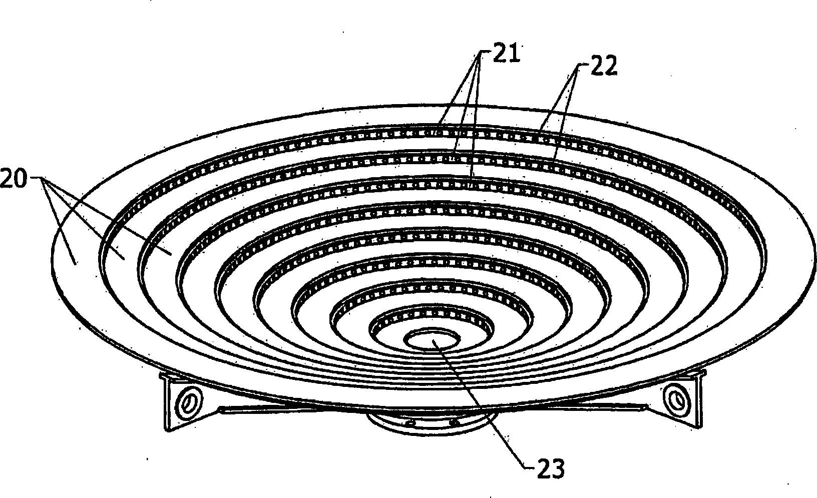
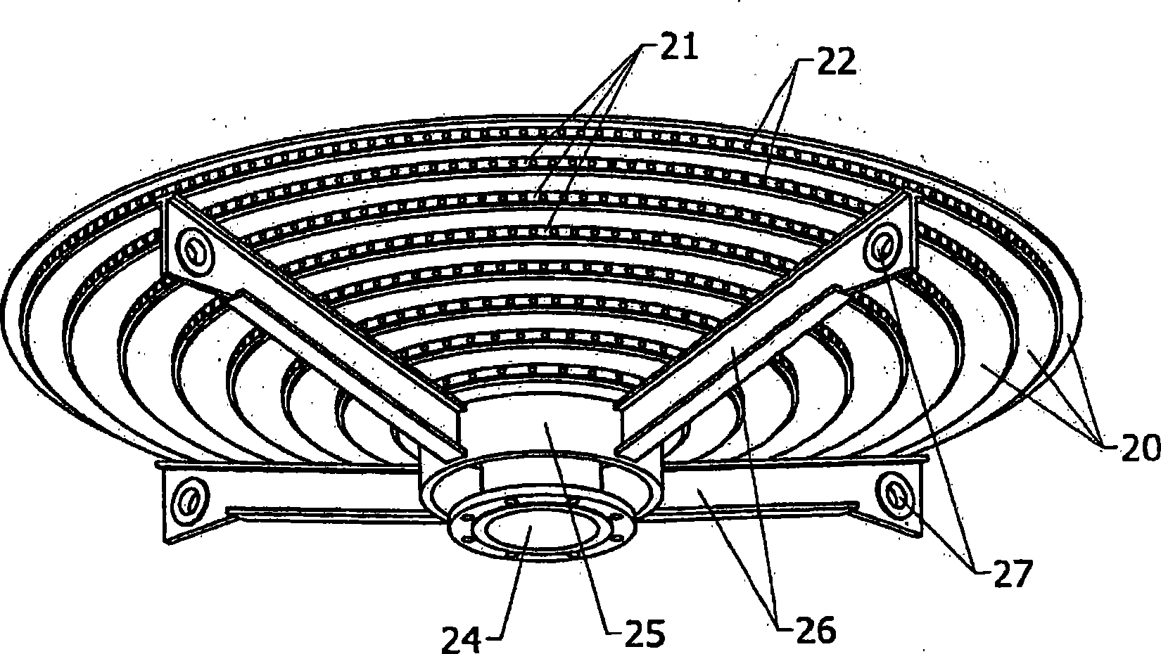
[0036] according to figure 2 and image 3 , the grating structure includes multiple layers of annular concentric plate rings arranged at different levels to form a downwardly tapering conical structure. The plate rings have different sized diameters. This structure includes two kinds of plate rings. The completely flat plate rings 20 are the first set of plate rings which form the basic structure of the grid. The first plate rings are most advantageously all horizontal. However, the grid structure also does not preclude the mounting of these plate rings in an oblique position. The slanted plate ring is then oriented towards the center of the cone of the structure.

[0037] The second ring 21 is the second set of rings which are located between the plate rings 20 which are completely flat. The thickness / height of the second ring generally corresponds to the mutual distance of the first plate rings from each other. The second plate ring has openings 22 to form horizontal...


PUM


Abstract

The present invention relates to a grid structure for a fluidized bed gasifier. The gasifier comprises an atmospheric or pressurized gasification reactor defined by vertical walls, wherein a fluidized bed is maintained in the reactor; a wind box located in the lower part of the gasifier below the reactor; and a grid that is arranged between the reactor and the wind box and comprises a number of substantially concentric plate rings. A first set of concentric plate rings are located at different levels to form a conical downwards tapering structure. The supporting structure of the first set of concentric plate rings comprises an annular supporting beam below the set of rings and radial supporting beams extending therefrom. The radial supporting beams are supported onto the walls of the wind box. The grid also comprises a second set of rings formed by plate rings arranged between the first rings. The second set of rings is provided with nozzle openings for leading air or other fluidizing gas from the wind box into the reactor.

Description

technical field [0001] The present invention relates to an air distribution grid for a fluidized bed gasifier. More specifically, the present application relates to a grid structure of a fluidized bed gasifier comprising: [0002] - an atmospheric or pressurized gasification reactor defined by vertical walls in which a fluidized bed is maintained; [0003] - the wind box, which is located in the lower part of the gasifier below the reactor; [0004] - A grid arranged between the reactor and the windbox on the upper surface of the windbox and comprising a plurality of substantially concentric plate rings. Background technique [0005] Fluidized bed gasifiers are used to generate gasification gas, for example from wood-based fuels. figure 1 A typical circulating fluidized bed gasifier is depicted. The gasifier unit in this case is a circulating fluidized bed gasifier 1 , ie a CFB gasifier. It includes a gasification reactor 2 , a grid 3 , a cyclone 4 and a cyclone return ...

Claims


Application Information

Patent Timeline
Patent Type & Authority Applications(China)
IPC IPC(8): B01J8/44F23C10/20C10J3/48C10J3/56C10J3/36
CPCC10J3/84F23C10/20B01J8/44C10J3/482F23C10/10C10J2200/152C10J3/36C10J3/56C10J3/34F23H17/08
Inventor 海基·维尔塔
Owner ANDRITZ AG
Why Eureka
Try Eureka