Dust collector

A technology for vacuum cleaners and suction nozzles, which is applied in the direction of vacuum cleaners, suction nozzles, mechanical devices for controlling suction, etc. It can solve problems such as harsh noises, and achieve the effects of ensuring driving stability, improving cleaning effects, and improving vibration effects

Active Publication Date: 2014-10-15
LG ELECTRONICS INC
View PDF9 Cites 4 Cited by
  • Summary
  • Abstract
  • Description
  • Claims
  • Application Information

AI Technical Summary

Problems solved by technology

and thus there is the concern of creating a very harsh noise

Method used


Image

  • Dust collector
  • Dust collector
  • Dust collector

Examples


Embodiment Construction

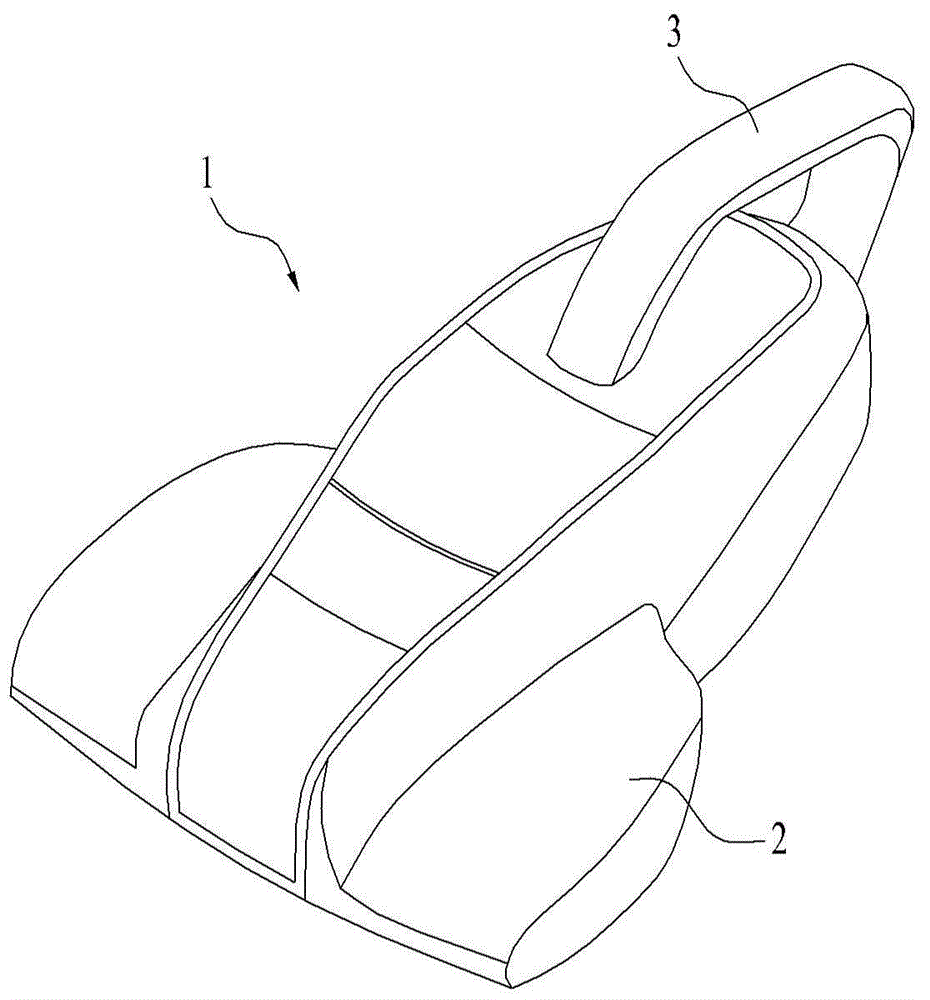
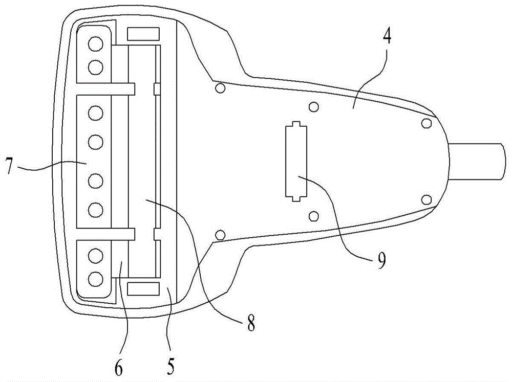
[0167] Hereinafter, a vacuum cleaner according to an embodiment of the present invention will be described in detail with reference to the accompanying drawings.

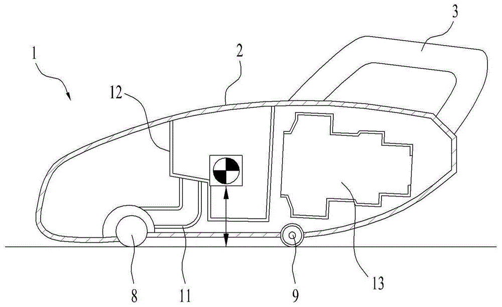
[0168] First, refer to Figure 5 to Figure 7 , the appearance of the vacuum cleaner 200 applicable to one embodiment of the present invention will be described. In this manual, the Figure 5 The left-right direction of the vacuum cleaner 200 shown, that is, the traveling direction of the vacuum cleaner 200 is defined as the front-rear direction. In addition, the both sides direction of the running direction of the cleaner 200 is defined as a left-right direction.

[0169] The cleaner 200 includes a body or main body 20 . That is, the main body 20 for forming the overall shape of the cleaner is included. Preferably, the above-mentioned main body 20 is formed to be inclined relative to the ground. That is, the centerline S of the main body 20 is inclined rearward with respect to the ground. Therefore, the closer...


PUM


Abstract

The present invention relates to a dust collector, and especially relates to a vacuum dust collector. According to an embodiment of the present invention, provided is a dust collector comprising a suction nozzle part body used for forming a suction nozzle part and a vibration system arranged at the suction nozzle part body, wherein the vibration system is elastically supported on the suction nozzle part body through an elastic component, and the vibration system comprises a motor for producing vibration.

Description

technical field [0001] The present invention relates to vacuum cleaners, and more particularly, to a vacuum cleaner. Background technique [0002] A vacuum cleaner is a device that has a fan motor inside to suck in air and dust from the outside and filter out the dust. Usually, this type of vacuum cleaner is called a vacuum cleaner. [0003] Generally, the vacuum cleaner includes a canister vacuum cleaner and an up-right vacuum cleaner, the main body of the canister vacuum cleaner and the suction nozzle are connected through an extension pipe or a connecting pipe, and the main body and the suction nozzle of the above-mentioned upright vacuum cleaner are directly connected. [0004] On the other hand, as a simple vacuum cleaner, a portable vacuum cleaner capable of cleaning while the user directly grasps the main body of the vacuum cleaner has been widely used. [0005] Recently, bedding vacuum cleaners capable of cleaning bedding have become widespread along with the impr...

Claims


Application Information

Patent Timeline
IPC IPC(8): A47L9/00A47L9/02
CPCA47L5/26A47L7/008A47L9/0072A47L9/0483
Inventor 李昌昱宋基龙河建镐
Owner LG ELECTRONICS INC
Why Eureka
Try Eureka