Medical radiation device
An irradiation device and irradiation technology, which is applied in the field of medical devices, can solve the problems of inconvenient use of space and treatment, and the large occupation of heat source irradiators, so as to achieve the effects of improving experience, improving utilization rate, and convenient storage
- Summary
- Abstract
- Description
- Claims
- Application Information
AI Technical Summary
Problems solved by technology
Method used
Image
Examples
no. 1 example
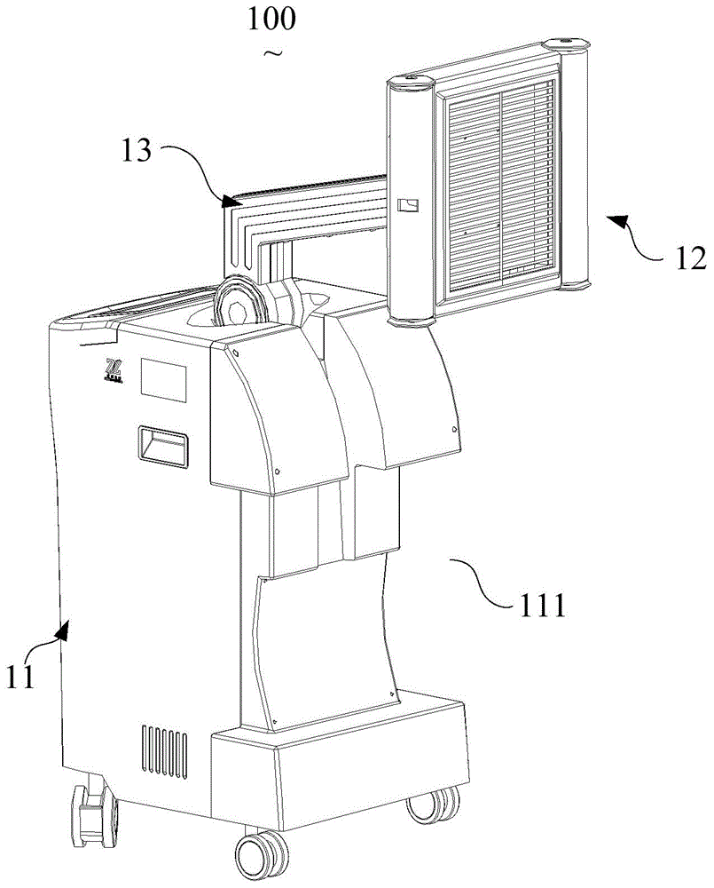
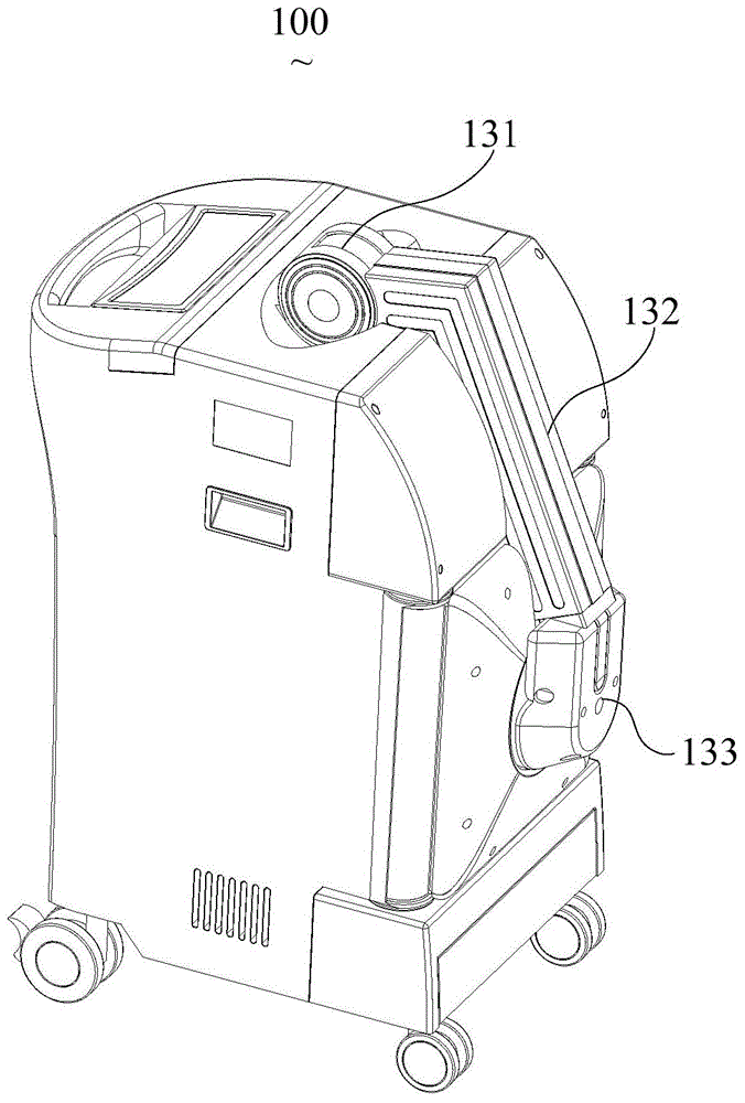
[0027] see figure 1 and figure 2 , figure 1 It is a schematic diagram of the expanded state structure of the medical irradiation device in the first embodiment of the invention, figure 2 Yes figure 1 Schematic diagram of the storage state structure of the medical irradiation device in . The medical irradiation device 100 provided by the present invention mainly includes a body 11 , an irradiation assembly 12 and a connection assembly 13 , wherein the irradiation assembly 12 mainly provides imitation biological waves or heat sources to treat organisms.
[0028] In this embodiment, a recess 111 is provided on the side of the machine body 11 , the irradiation assembly 12 matches the recess 111 , and the connecting assembly 13 rotatably connects the irradiation assembly 12 and the body 11 . like figure 2 As shown, when the irradiation assembly 12 is stored, the irradiation assembly 12 is accommodated in the recess 111 . like figure 1 As shown, when the irradiation assemb...
no. 2 example
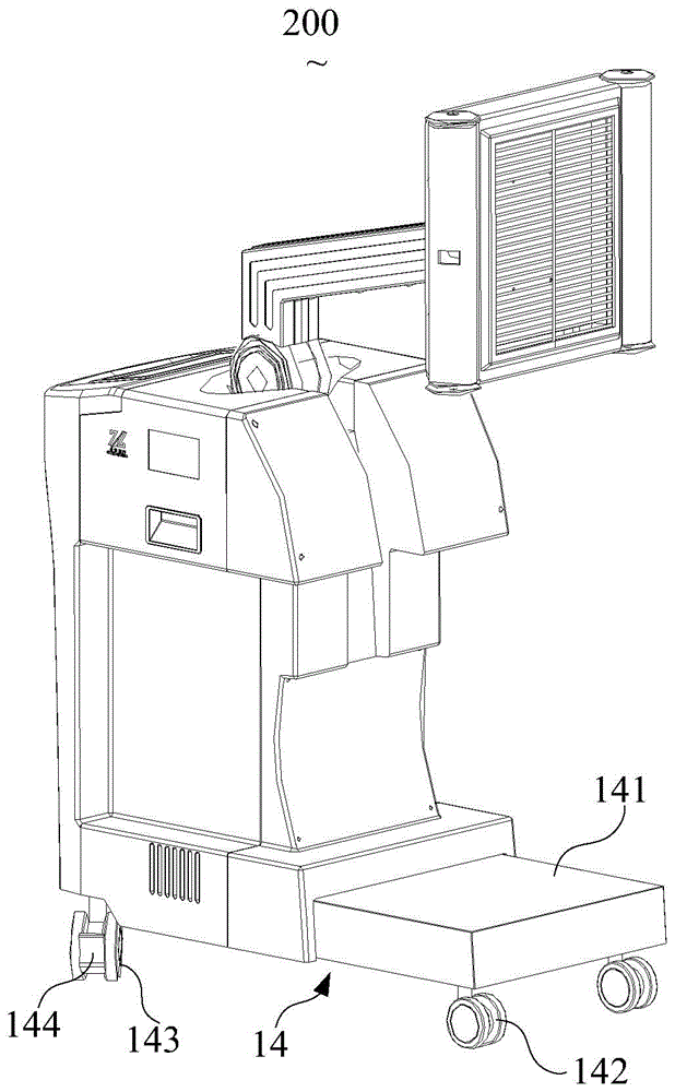
[0033] Please also refer to image 3 , image 3 It is a structural schematic diagram of the expanded state of the medical irradiation device in the second embodiment of the present invention. The medical irradiation device 200 in this embodiment is substantially the same as the first embodiment, except that the medical irradiation device 200 in this embodiment includes a telescopic base 14 .
[0034] The telescopic base 14 in this embodiment is arranged at the bottom of the machine body 11. When the irradiation assembly 12 is stored, the telescopic base 14 is in a retracted state. The center of gravity is stable.
[0035] The telescopic base 14 includes a telescopic bracket 141 , a front wheel 142 , a rear wheel 143 and a brake handle 144 . The telescopic bracket 141 is telescopically connected to the bottom of the body 11, the front wheel 142 is arranged at the front end of the telescopic bracket 141, the rear wheel 143 is arranged at the rear end of the bottom of the body...
no. 3 example
[0038] Please also refer to Figure 4 and Figure 5 , Figure 4 It is a schematic diagram of the expanded state structure of the medical irradiation device in the third embodiment of the present invention, Figure 5 Yes Figure 4 Schematic diagram of the storage state structure of the medical irradiation device in . The medical irradiation device 300 of this embodiment is substantially the same as that of the second embodiment, except that the irradiation assembly 12 in this embodiment includes a first irradiation unit 121 , a second irradiation unit 122 and a third irradiation unit 123 , and can be respectively stored in the left concave portion 115 , the front concave portion 114 and the right concave portion 116 of the body 11 .
[0039] like Figure 4As shown, the body 11 includes a front shell 112 and a rear shell 113, the front shell 112 is provided with a front recess 114, the rear shell 113 is fastened with the front shell 112, the rear shell 113 is provided with ...
PUM
 Abstract
Description
Claims
Application Information
 - R&D
- Intellectual Property
- Life Sciences
- Materials
- Tech Scout
- Unparalleled Data Quality
- Higher Quality Content
- 60% Fewer Hallucinations
Browse by: Latest US Patents, China's latest patents, Technical Efficacy Thesaurus, Application Domain, Technology Topic, Popular Technical Reports.
© 2025 PatSnap. All rights reserved.Legal|Privacy policy|Modern Slavery Act Transparency Statement|Sitemap|About US| Contact US: help@patsnap.com


