Flip stand
What is Al technical title?
Al technical title is built by PatSnap Al team. It summarizes the technical point description of the patent document.
A technology of turning racks and turning discs, applied in the field of turning racks, can solve problems such as hidden safety hazards, difficulty in positioning workpieces, time-consuming and labor-intensive problems, and achieve the effects of eliminating hidden safety hazards, reducing labor intensity, and improving production efficiency
Active Publication Date: 2015-12-23
南通中集顺达集装箱有限公司 +1
View PDF6 Cites 0 Cited by
Summary
Abstract
Description
Claims
Application Information
AI Technical Summary
This helps you quickly interpret patents by identifying the three key elements:
Problems solved by technology
Method used
Benefits of technology
Problems solved by technology
[0004] However, this kind of overturning frame is mainly rotated manually, which is time-consuming and labor-intensive; the inertia of the welding workpiece is large when rotating, and because there is no mechanical brake, the positioning of the workpiece is difficult; Time-consuming and labor-intensive, there are also potential safety hazards
Method used
Image
Click on the blue label to locate the original text in one second.
Reading with bidirectional positioning of images and text.
Examples
Embodiment Construction
[0025] In order to further illustrate the principle and structure of the present invention, preferred embodiments of the present invention will now be described in detail with reference to the accompanying drawings.
[0026] When describing the orientation in the present invention, the direction in which the welded workpiece flows is the same or the opposite direction is taken as the longitudinal direction, and the orientation perpendicular to the flow direction of the welded workpiece in the horizontal plane is taken as the transverse direction.
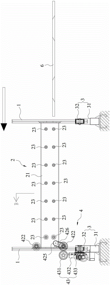
[0027] refer to image 3 and Figure 4 , The reversing frame of the present invention includes: two reversing discs 1 , a conveying frame 2 , two rollers 3 , a transmission drive mechanism 4 and a reversing drive mechanism 5 .
[0028] Both turning disks 1 are in a circular structure, and at least one turning disk 1 is provided with a circle of conveyor belt on its outer peripheral surface. The conveyor belt can be a belt or a cha...
PUM
Abstract
The invention relates to a turnover frame, which comprises two turnover discs, two support rolls, a conveying frame, a turnover driving mechanism and a transmission driving mechanism, wherein each turnover disc is respectively of a circular structure, the peripheral surface of at least one turnover disc is provided with a circle of conveying belt, the two support rolls are respectively arranged at the bottoms of the turnover discs, each turnover disc can rotate relative to each support roll, the conveying frame comprises a machine frame, an upper row of conveying rolls and a lower row of conveying rolls, the upper and lower rows of conveying rolls are arranged on the machine frame, the two longitudinal ends of the machine frame are respectively connected with the two turnover discs, the turnover driving mechanism comprises a power input wheel and a driver, the driver is connected with the power input wheel, the power input wheel is in contact with each conveying belt, the driver drives the power input wheel to rotate, and then further drives the turnover discs to rotate, the transmission driving mechanism is used for driving the conveying rolls on the conveying frame to rotate, and then welding workpieces are longitudinally conveyed. The turnover frame has the advantage that the workpieces are automatically turned over, and are automatically and longitudinally conveyed, so the labor strength of a workshop is reduced, the production efficiency is improved, and the safety hidden hazards of manual operation are eliminated.
Description
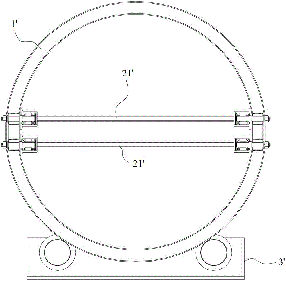
technical field [0001] The invention relates to the field of machinery, in particular to an overturn frame for welding workpieces on containers. Background technique [0002] A container is a large-scale loading container with certain strength, rigidity and specifications, which is specially used for turnover. In order to improve the service life, the container usually adopts a steel structure, so welding is the main workload during the production of the container. In order to facilitate welding by workers, some welding tires usually use a flip frame to turn the weld seam of the workpiece to be welded to an angle that is convenient for welding. [0003] refer to figure 1 and figure 2 , the currently commonly used reversing frame includes: two circular reversing disks 1' and a transfer frame 2' connected between the two reversing disks 1'. The two ends of the transmission rack 2' are respectively connected to the two turning discs 1', and two rows of transmission rollers ...
Claims
Application Information
Patent Timeline
Application Date:The date an application was filed.
Publication Date:The date a patent or application was officially published.
First Publication Date:The earliest publication date of a patent with the same application number.
Issue Date:Publication date of the patent grant document.
PCT Entry Date:The Entry date of PCT National Phase.
Estimated Expiry Date:The statutory expiry date of a patent right according to the Patent Law, and it is the longest term of protection that the patent right can achieve without the termination of the patent right due to other reasons(Term extension factor has been taken into account ).
Invalid Date:Actual expiry date is based on effective date or publication date of legal transaction data of invalid patent.