Push fork locking structure for hair scissors

A technology of locking structure and haircutting scissors, which is applied in metal processing and other directions, can solve the problems of troublesome operation, high cost, cumbersome operation, etc., and achieve the effect of simple operation, convenient operation and reliable structure

Active Publication Date: 2014-10-15
NINGBO ZHENHE ELECTRICAL EQUIP
View PDF6 Cites 8 Cited by
  • Summary
  • Abstract
  • Description
  • Claims
  • Application Information

AI Technical Summary

Problems solved by technology

The moving knife is pushed by a push fork, but when the push fork moves back and forth to adjust the moving knife, after the position is adjusted in place, there must be a positioning device or mechanism to position the push fork so that the moving knife and the static knife can work normally. In the prior art, the structures of the devices or mechanisms used for positioning...

Method used


Image

  • Push fork locking structure for hair scissors
  • Push fork locking structure for hair scissors
  • Push fork locking structure for hair scissors

Examples


Embodiment Construction

[0024] The present invention will be further described below in conjunction with the accompanying drawings and specific embodiments.

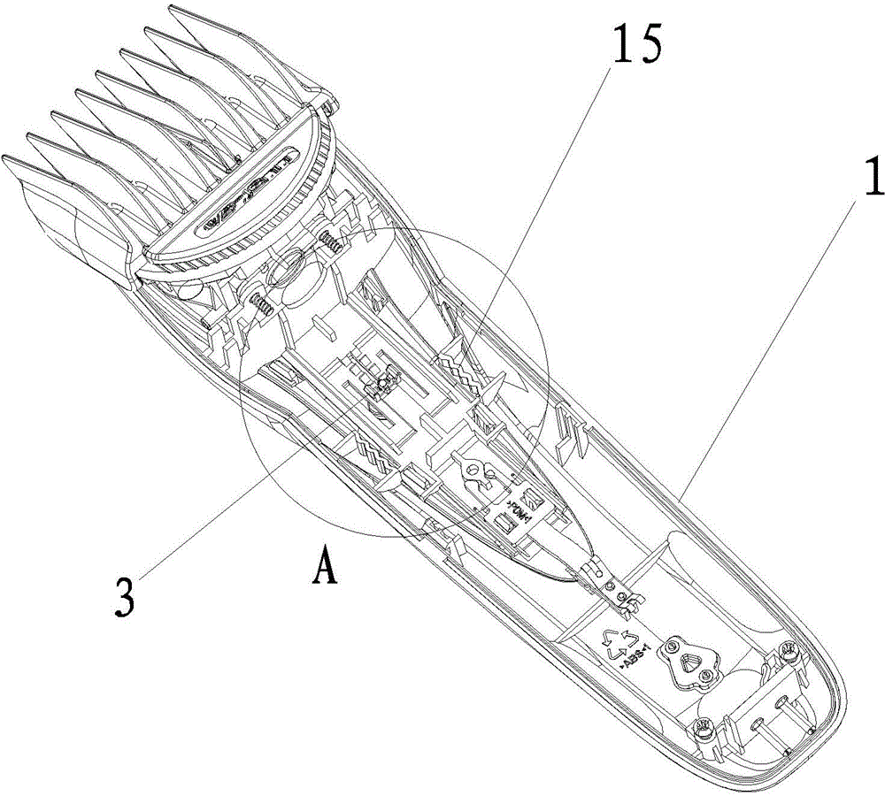
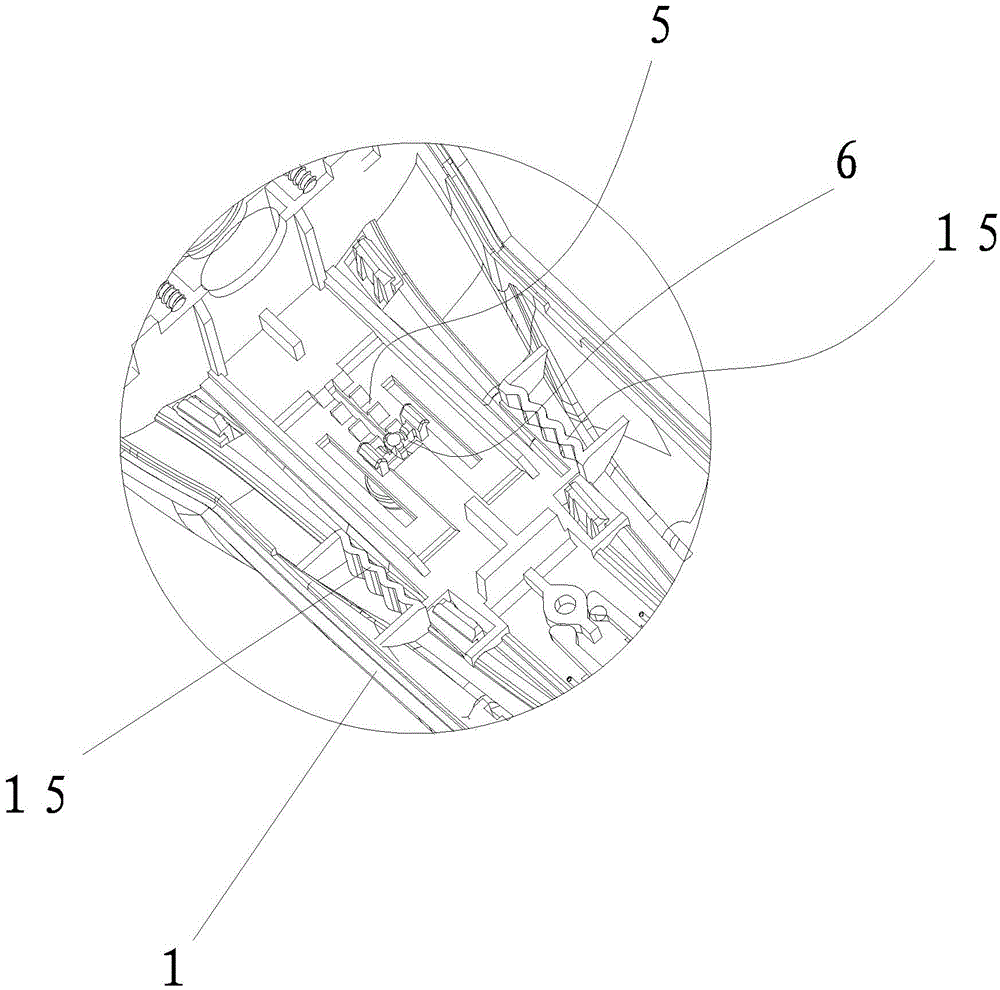
[0025] Such as figure 1 , figure 2 , image 3 , Figure 4 , Figure 5 , Figure 6 , Figure 7 , Figure 8 , Figure 9 , Figure 10 As shown, the push fork locking structure of the barber scissors of the present invention includes a casing 1, a push fork 2 positioned in the casing 1 for pushing the movable knife, and an adjustment push key 18 installed outside the casing 1 for pushing the push fork 2 to move And the lock button 3 that moves synchronously with the adjustment push key 18, the adjustment push key 18 is connected with the push fork 2, and the lock button 3 is provided with a locking structure between the push forks 2, and the push fork 2 is pushed by the adjustment push key 18. After moving to a suitable position, there is a locking structure to lock and fix the push fork 2. Generally speaking, the shell 1 is composed of a...


PUM


Abstract

The invention relates to a push fork locking structure for hair scissors. The push fork locking structure comprises a housing, a push fork, a regulating push key and a lock catch button, wherein the push fork is positioned in the housing and is used for pushing a moving blade; the regulating push key is arranged outside the housing and is used for pushing the push fork to move; the lock catch button moves synchronously with the regulating push key; the push fork is in sliding fit with the housing; the inner side wall of the housing is provided with tooth spaces; the side edges of the push fork are provided with limit control rods matched with the tooth spaces; a locking groove is formed at the positions, which correspond to the lock catch button, on the push fork; a lock catch engaged with the locking groove is arranged on the lock catch button; a returning spring is arranged between the lock catch button and the push fork.

Description

Technical field: [0001] The invention relates to hair cutting equipment, in particular to a locking structure of a push fork of hair cutting scissors. Background technique: [0002] Most of the hair clippers now have the ability to adjust the length of the haircut, which is realized by adjusting the distance between the moving knife and the static knife. The moving knife is pushed by a push fork, but when the push fork moves back and forth to adjust the moving knife, after the position is adjusted in place, there must be a positioning device or mechanism to position the push fork so that the moving knife and the static knife can work normally. In the prior art, the structures of the devices or mechanisms for positioning the push forks are different, and the effects also have their own advantages, but their respective shortcomings are also obvious, and some operations are relatively cumbersome. In some cases, the correlation between the various parts is too strong. As long a...

Claims


Application Information

Patent Timeline
IPC IPC(8): B26B19/38
Inventor 王保安戴沪杰
Owner NINGBO ZHENHE ELECTRICAL EQUIP
Why Eureka
Try Eureka