Heat-exchange tube

A heat exchange tube and tube body technology, which is applied in heat exchange equipment, tubular elements, lighting and heating equipment, etc., can solve the problem of increasing the heat exchange area, achieve the effect of increasing the evaporation rate and improving the heat exchange effect of falling film evaporation

Inactive Publication Date: 2013-04-24
JIANGSU CUILONG PRECISION COPPER TUBE CORP
View PDF7 Cites 18 Cited by
  • Summary
  • Abstract
  • Description
  • Claims
  • Application Information

AI Technical Summary

Problems solved by technology

Not limited to the heat transfer tubes disclosed in these patents Since the secondary grooves are only formed at the ends of the fins, the increase in heat transfer area is very limited

Method used


Image

  • Heat-exchange tube
  • Heat-exchange tube

Examples


Embodiment 1

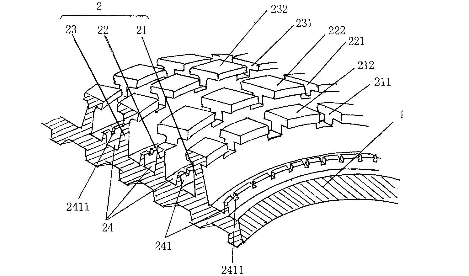
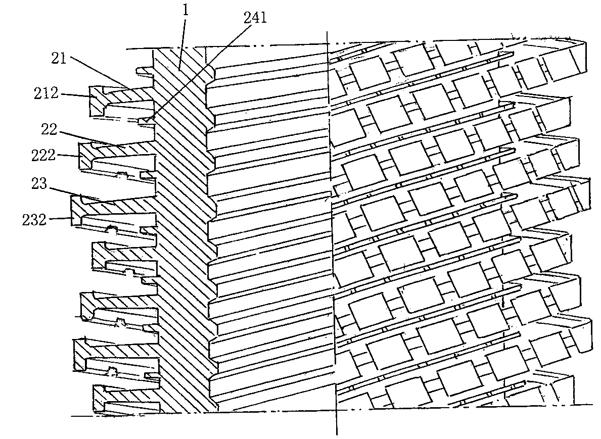
[0019] See figure 1 with figure 2 , a pipe body 1 is provided, and a spiral fin group 2 is formed on the outer wall of the pipe body 1. The spiral fin group 2 is in a spiral state and surrounds the circumferential direction of the pipe body 1 from one end of the pipe body 1 in the length direction. Continuously extend to the other end of the tube body 1 in a cyclical and repeated manner. In this embodiment, the helical fin group 2 is composed of first, second helical fins 21, 22 and third helical fins 23, and one of the first, second and third helical fins 21, 22, 23 The distance between them is the same.

[0020] It can be seen from the figure that the first groove 211 intersecting with the first spiral fin 21 is spaced apart on the upper part of the aforementioned first spiral fin 21, and the first spiral fin between two adjacent first grooves 211 The material at the top of the fin 21 extends or shifts to both sides to form a first T-shaped fin platform 212 whose c...

Embodiment 2

[0026] Only change the difference between the second distance and the first distance, that is, the value of the second distance minus the first distance, to 0.3㎜, and change the difference between the third distance and the second distance, that is, the value of the third distance minus the second distance to 0.05㎜; change the height of the first helical fin 21 to 0.5㎜, the height of the second helical fin 22 to 0.8㎜, and the height of the third helical fin 22 to 0.85㎜; change the width of the fin groove 24 to Change the height of the small protruding fins 241 to 0.4 mm, change the distance between the top grooves 2411 of two adjacent small protruding fins to 0.2 mm, and change the width of the top grooves 2411 of the small protruding fins to 0.05 mm, Change the depth to 0.1mm; change the width and depth of the first, second, and third grooves 211, 221, and 231 to 0.1mm and 0.5mm respectively; change the distance between two adjacent first grooves 211, The distance between t...

Embodiment 3

[0028] Only change the difference between the second distance and the first distance to 0.17mm, change the difference between the third distance and the second distance to 0.2mm; change the height of the first helical fin 21 to 0.6mm, and change the height of the second helical fin The height of 22 is 0.77㎜, the height of the third helical fin 22 is 0.97㎜; the width of the fin groove 24 is changed to 0.12㎜, the height of the protruding small fin 241 is changed to 0.05㎜, and the two adjacent protrusions Change the pitch of the small fin top groove 2411 to 0.7mm, change the width and depth of the small fin top groove 2411 to 0.08mm and 0.06mm respectively; change the first, second and third grooves 211, 221 Change the width and depth of 231 to 0.25㎜ and 0.1㎜ respectively; change the distance between two adjacent first grooves 211, the distance between two adjacent second grooves 221 and the distance between two adjacent third The spacing between the grooves 231 is changed to 0...


PUM


Abstract

The invention discloses a heat-exchange tube and belongs to the field of heat enhancement of heat transfer and energy saving. The heat-exchange tube comprises a tube body and a helical fin group, wherein the helical fin is formed by a first helical fin, a second helical fin and a third helical fin, first grooves are formed on the upper portion of the first helical fin, helical fin top portions among the first grooves form first T-shaped fin platforms; second grooves are formed on the upper portion of the second helical fin, helical fin top portions among the second grooves form second T-shaped fin platforms; third grooves are formed on the upper portion of the third helical fin, and helical fin top portions among the third grooves form third T-shaped fin platforms. The heat-exchange tube is characterized a first distance between the top surfaces of the first T-shaped fin platforms and a fin root portion of the first helical fin is smaller than a second distance between the top surfaces of the second T-shaped fin platforms and a fin root portion of the second helical fin, the second distance is smaller than a third distance between the top surfaces of the third T-shaped fin platforms and a fin root portion of the third helical fin, and find grooves are formed in the spaces between the first helical fin and the second helical fin, the second helical fin and the third helical fin, and between the third helical fin and the first helical fin. By the aid of the heat-exchange tube, heat exchange efficiency for falling film evaporation is improved.

Description

technical field [0001] The invention belongs to the technical field of heat transfer enhancement and energy saving, and in particular relates to a heat exchange tube used in air-conditioning and refrigeration systems. Background technique [0002] In the prior art, in order to improve the heat exchange efficiency of heat exchange tubes used in air-conditioning and refrigeration systems, low-finned tubes are generally used to increase the heat exchange area, and at the same time enhance the heat exchange surface to enhance the fluid disturbance to enhance the heat exchange effect. Chinese utility model patent ZL99228089.3, Chinese invention patent ZL95121709.7 and Chinese utility model patent ZL02232596.4 disclose a heat transfer tube with a three-dimensional low-fin structure. A group of main grooves are cut out on the tube wall to form fins. , and then cut a set of intersecting spiral grooves (secondary grooves) on the fins to form tooth-shaped spiral fins. Not limited to ...

Claims


Application Information

Patent Timeline
Patent Type & Authority Applications(China)
IPC IPC(8): F28F1/36
Inventor 周浩平时明华张国锋景晓伟
Owner JIANGSU CUILONG PRECISION COPPER TUBE CORP
Why Eureka
Try Eureka