
Metal and dust removing device for cotton

A technology for metal dust and cotton, applied in the field of cotton metal dust impurity removal device, can solve the problems of high impurity removal cost, low impurity removal efficiency, affecting cotton quality, etc., and achieves the effect of simple structure and high removal efficiency

Inactive Publication Date: 2014-10-15
WUJIANG TEXTILE SCI & TECH CENT
View PDF7 Cites 8 Cited by
  • Summary
  • Abstract
  • Description
  • Claims
  • Application Information

AI Technical Summary

Problems solved by technology

[0002] In the process of cotton picking, it is often mixed with many impurities and dust, which affects the quality of cotton. At the same time, when cotton is produced in the equipment, it is often mixed with some metal impurities, which will also cause serious damage to the subsequent textile production. Great harm, while affecting the quality of cotton, so these dust particles and metal impurities need to be removed in time
However, in the current cotton production, these two kinds of impurities need to be removed separately by different equipment, especially metal impurities need special testing equipment, cotton machinery often adopts the air blowing method when transporting cotton, and the metal impurity removal device of cotton machinery usually The cotton is conveyed by wind, and the inside of the conveyed cotton is detected by a metal detector. If there are metal impurities in the cotton, the entire part of the cotton containing metal is sent away through the air duct, and then further impurities are removed, and metal impurities are removed. The process is more complicated, and the metal impurities and dust impurities in the cotton machinery are removed separately, which makes the overall impurity removal efficiency lower and the cost of impurity removal higher

Method used


Image

  • Metal and dust removing device for cotton

Examples


Embodiment Construction

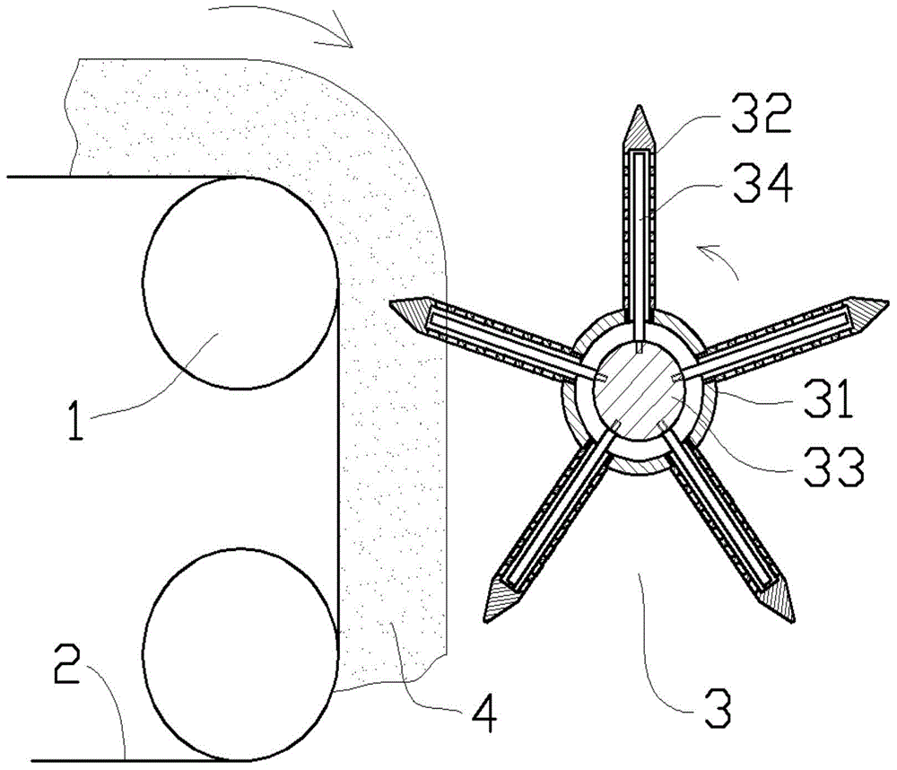
[0009] Such as figure 1 As shown in the embodiment, the cotton metal dust removal device includes a conveyor roller 1 assembled up and down, a conveyor belt 2 is installed between the two conveyor rollers 1, and the vertical side of the conveyor belt 2 is equipped with a conveyor belt parallel to the conveyor roller 1. The licker-in roller 3, the licker-in roller 3 comprises a drum-shaped housing 31, the housing 31 is provided with a circular tube-shaped stabbing tube 32, and the inside of the stabbing tube 32 communicates with the inside of the housing 31, The thorn tube 32 is vertically fixed on the surface of the housing 31, and the housing 31 is equipped with a central shaft 33 on the axis, and the central shaft 33 is fixed with a magnetic bar 34 that goes deep into the inside of the thorn tube 32. Through holes are evenly distributed on the surface of the thorn tube 32 , and an annular cavity is formed between the housing 31 and the central shaft 33 , and the annular cavi...


PUM


Abstract

The invention provides a metal and dust removing device for cotton. The metal and dust removing device comprises conveying rollers assembled in an vertical direction, a conveying belt is assembled between the two conveying rollers, a licker-in is assembled on the lateral side in the vertical direction of the conveying belt and comprises a shell, round-pipe-shaped licker-in pipes are uniformly distributed on the shell, the inside of each licker-in pipe is communicated with that of the shell, and the licker-in pipes are vertically fixed on the surface of the shell; a central shaft is assembled on the axis of the shell, magnetic rods entering inside the licker-in pipes are fixed on the central shaft, through holes are uniformly distributed on the surface of each licker-in pipe, an annular cavity is formed between the shell and the central shaft and connected with an air incoming end of a fan through a pipeline, and the shell and the central shaft are driven to synchronously rotate by a transmission device. The metal and dust removing device can remove metal and dust in the process of belt conveying and is simple in structure and high in overall impurity removing efficiency.

Description

technical field [0001] The invention relates to the technical field of textile machinery, in particular to a cotton metal dust impurity removal device. Background technique [0002] In the process of cotton picking, it is often mixed with many impurities and dust, which affects the quality of cotton. At the same time, when cotton is produced in the equipment, it is often mixed with some metal impurities, which will also cause serious damage to the subsequent textile production. Great harm, while affecting the quality of cotton, so these dust particles and metal impurities need to be removed in time. However, in the current cotton production, these two kinds of impurities need to be removed separately by different equipment, especially metal impurities need special testing equipment, cotton machinery often adopts the air blowing method when transporting cotton, and the metal impurity removal device of cotton machinery usually The cotton is conveyed by wind, and the inside of...

Claims


Application Information

Patent Timeline
IPC IPC(8): D01G9/06D01G9/08
Inventor 杨伯娟钱末丫戴晨
Owner WUJIANG TEXTILE SCI & TECH CENT
Learn More