
Guiderail device and method for pouring slope roof

A technology of guide rail device and sloping roof, which is applied in the processing of building materials, roofs, buildings, etc. It can solve problems such as flatness not meeting the construction accuracy requirements of the waterproof layer, concrete slipping, and vibration not being dense, so as to avoid construction quality Problems, prevention of slippage, effect of easy pouring

Active Publication Date: 2014-10-15
WUHAN HANYANG MUNICIPAL CONSTR GRP CO LTD
View PDF6 Cites 16 Cited by
  • Summary
  • Abstract
  • Description
  • Claims
  • Application Information

AI Technical Summary

Problems solved by technology

However, in the process of pouring concrete for sloping roofs, vibrating rods are required to vibrate the concrete. This process is prone to concrete slippage and segregation, which makes the vibrating not compact and difficult to pour.
In addition, hanging ropes are auxiliary facilities for construction. Concrete workers control the height of the floor according to the hanging wires. The process is complicated and difficult to operate. The flatness cannot meet the construction accuracy requirements of the waterproof layer, and another leveling layer needs to be made, resulting in greater waste. And the construction period is long, if we can improve the cast-in-place method of the sloping roof, make the flatness of the sloping roof meet the construction requirements of the waterproof layer, cancel the leveling layer, and shorten the construction period, it will produce better economic and social benefits

Method used


Image

  • Guiderail device and method for pouring slope roof
  • Guiderail device and method for pouring slope roof

Examples


Embodiment Construction

[0035] The present invention will be described in further detail below in conjunction with the accompanying drawings and embodiments.

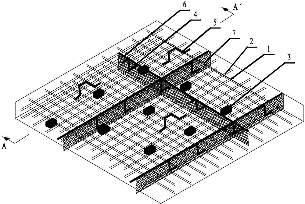
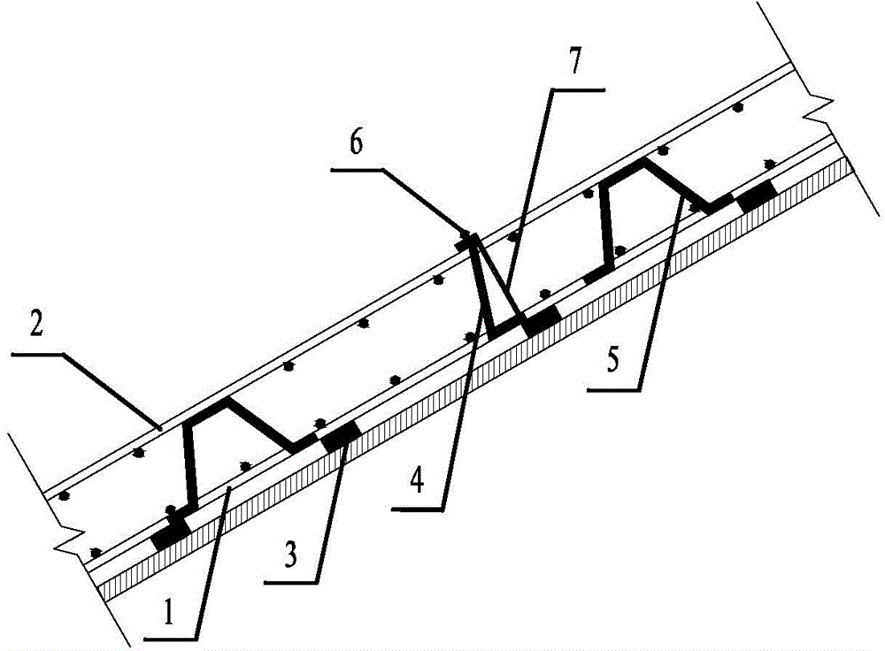
[0036] Such as figure 1 with figure 2 As shown, a guide rail device for pouring construction of a sloping roof includes a slab bottom steel bar 1 laid on the top surface of the sloping roof formwork, and a slab surface steel bar 2 arranged opposite to the slab bottom steel bar 1 is arranged above the slab bottom steel bar 1 . A plurality of pads 3 are arranged between the steel bars 1 at the bottom of the slab and the formwork of the sloping roof. The pads 3 are concrete blocks, which are used to carry the steel bars 1 at the bottom of the slab and form a sufficient protective layer specified in the design, and the adjacent pads 3 The spacing between them is 1m. A plurality of horse stool bars 5 are arranged between the bottom reinforcement 1 and the board surface reinforcement 2, and the plurality of horse stool bars 5 are arranged in a qu...


PUM

PropertyMeasurementUnit
Wire diameteraaaaaaaaaa
Apertureaaaaaaaaaa

Abstract

The invention discloses a guiderail device and method for pouring a slope roof and relates to the technical field of building engineering construction. The guiderail device comprises plate-bottom steel reinforcing bars laid on the top surface of the form board of the slope roof. Plate-surface steel reinforcing bars opposite to the plate-bottom steel reinforcing bars are disposed above the plate-bottom steel reinforcing bars. A plurality of cushion blocks are disposed between the plate-bottom steel reinforcing bars and the form board of the slope roof. A plurality of horse stool steel reinforcing bars and a plurality rows of guiderail support steel reinforcing bars are disposed between the plate-bottom steel reinforcing bars and the plate-surface steel reinforcing bars. A guiderail steel reinforcing bar is fixedly connected to the top surface of each row of guiderail support steel reinforcing bars, and a steel wire mesh is fixedly connected to the bottom of the guiderail steel reinforcing bar. When the guiderail device is used for pouring, the plate-bottom steel reinforcing bars are laid first, the cushion blocks are placed between the plate-bottom steel reinforcing bars and the form board, then the horse stool steel reinforcing bars are fixed and the plate-surface steel reinforcing bars are laid, the guiderail support steel reinforcing bars are disposed and the guiderail steel reinforcing bars are laid, the steel wire meshes are mounted below the guiderail steel reinforcing bars, and finally concrete pouring can be performed. The guiderail device has the advantages that the guiderail device is easy in concrete pouring and dense in vibration, construction progress is accelerated, and construction cost is lowered.

Description

technical field [0001] The invention relates to the technical field of building engineering construction, in particular to a guide rail device and method for pouring construction of sloping roofs. Background technique [0002] At present, sloping roofs are widely used because of their beautiful appearance and smooth drainage without water leakage. However, due to the different elevations of the sloping roof, the difficulty of concrete pouring and vibration, and the high technical requirements for the flatness of the slab surface, it is difficult to control the construction quality. The existing construction technology generally adopts hanging ropes to control the elevation of the sloping roof, the concrete slump is controlled at 10-12 cm, and the concrete is poured in sections (within 4 meters) in layers, and manually smoothed and maintained. After the construction of the cast-in-place sloping roof slab is completed, a leveling layer needs to be made on the slab so that the...

Claims


Application Information

Patent Timeline
IPC IPC(8): E04G21/02E04B7/02
Inventor 陈世文胡红胜虞志鹏吕国鹏郑佳
Owner WUHAN HANYANG MUNICIPAL CONSTR GRP CO LTD
Learn More