Rotating devices and fluid motors, engines, compressors and pumps using them

A technology for rotating devices and cylinders, which is applied in the field of fluid motors, engines, compressors and pumps. It can solve the problems of not applying fluid motors and engines, and restricting the application of eccentric rotor structures, so as to achieve high-efficiency and low-consumption rotary seals and improve work reliability. Performance and life, and the effect of improving operating efficiency

Active Publication Date: 2016-05-25
BEIJING ROSTAR TECH
View PDF10 Cites 0 Cited by
  • Summary
  • Abstract
  • Description
  • Claims
  • Application Information

AI Technical Summary

Problems solved by technology

However, so far, the above-mentioned eccentric rotor structure has not been applied to the field of fluid motors and engines
The reason is that the problem of cylinder sealing under high frequency and oil-free working environment has not been solved for a long time, which greatly limits the application of this kind of eccentric rotor structure in scenarios such as engines and fluid motors.

Method used


Image

  • Rotating devices and fluid motors, engines, compressors and pumps using them
  • Rotating devices and fluid motors, engines, compressors and pumps using them
  • Rotating devices and fluid motors, engines, compressors and pumps using them

Examples


Embodiment Construction

[0036] In order to make the object, technical solution and advantages of the present invention clearer, the present invention will be described in further detail below in conjunction with specific embodiments and with reference to the accompanying drawings. It should be noted that, in the drawings or descriptions of the specification, similar or identical parts all use the same figure numbers. Implementations not shown or described in the accompanying drawings are forms known to those of ordinary skill in the art. While illustrations of parameters containing particular values ​​may be provided herein, it should be understood that the parameters need not be exactly equal to the corresponding values, but rather may approximate the corresponding values ​​within acceptable error margins or design constraints. In addition, the directional terms mentioned in the following embodiments, such as "upper", "lower", "front", "rear", "left", "right", etc., are only referring to the directi...


PUM


Abstract

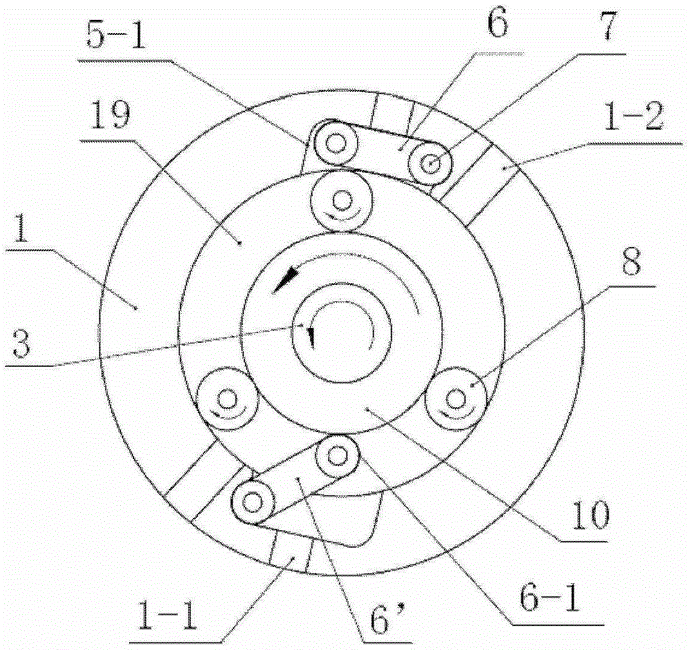
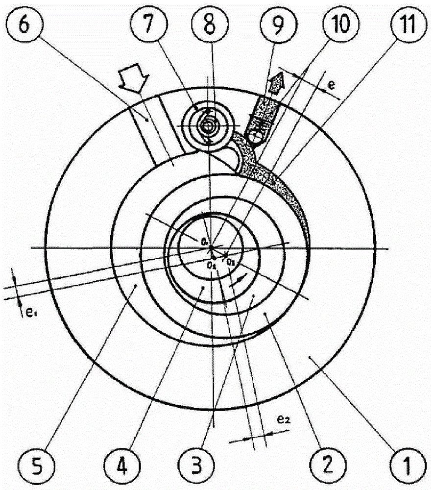
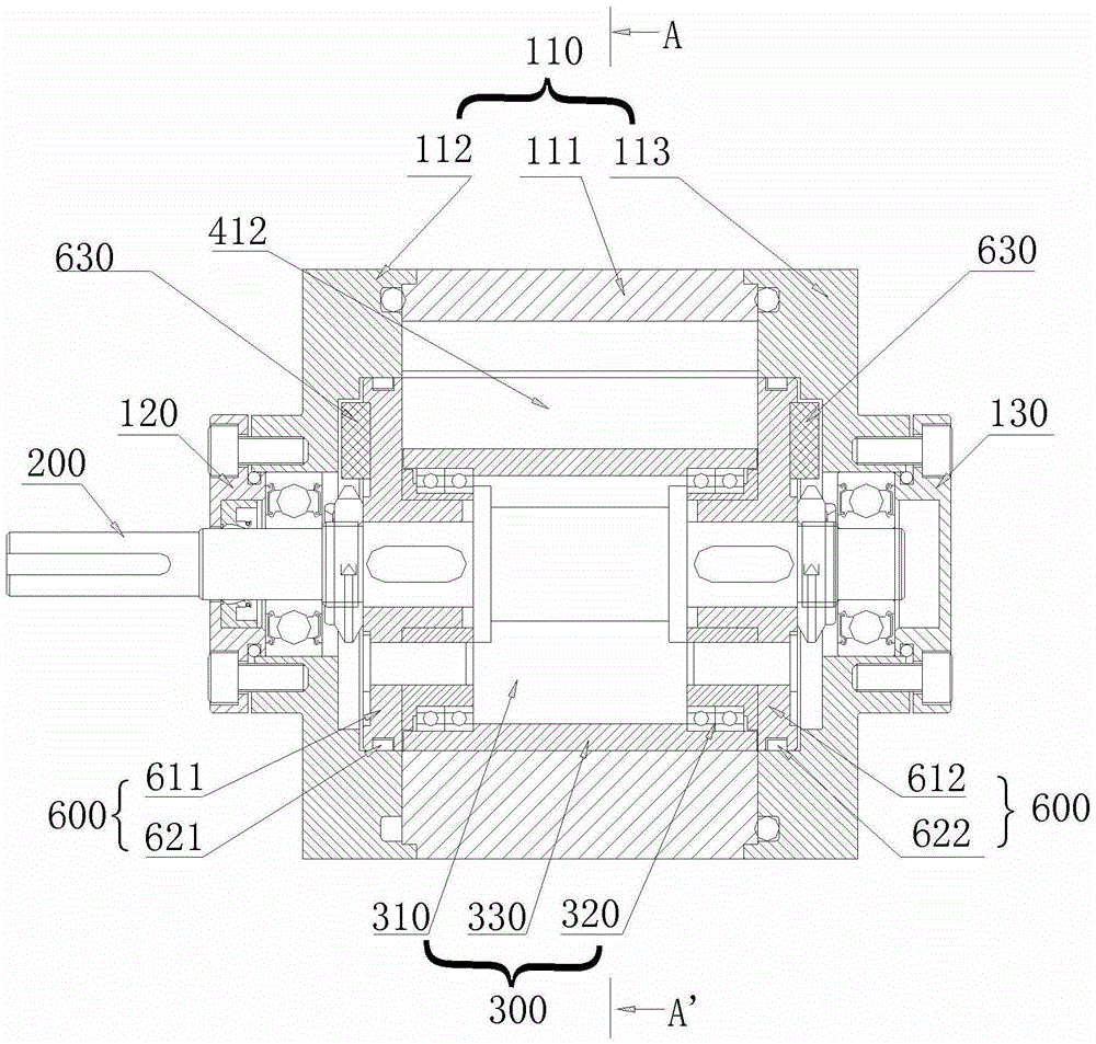
Disclosed are a rotation device, and a fluid motor, an engine, a compressor and a pump comprising the rotation device. In the rotation device, inlaying grooves for fixing expansion piston rings (621, 622) are formed in the middle of the external cylindrical surfaces of two star wheel fixed flanges (611, 612), the expansion piston rings (621, 622) are in seal fit with the inner cylindrical surface of a cylinder and have gaps of a predetermined size relative to the bottoms and sidewalls of the inlaying grooves, a tiny amount of fluid leaking from the gaps is driven by the rotary motion of the star wheel fixed flanges (611, 612) to form gas film lubrication or fluid film lubrication, thus noncontact seal for a cylindrical inner cavity is realized, and the rotation device can operate in a high-frequency, oil-free working environment.

Description

technical field [0001] The invention relates to the technical field of fluid machinery, in particular to a rotating device and a fluid motor, engine, compressor and pump using the rotating device. Background technique [0002] A power conversion device is an energy conversion device that converts mechanical energy and fluid pressure energy, including, for example, an engine, a fluid motor, a compressor, and a pump. In the traditional field of engines, there are mainly mechanical structures such as reciprocating piston four-stroke engines, triangular rotor engines, and gas turbines. In the traditional field of fluid motors, there are mainly mechanical structures such as piston type, vane type, and gear type. In the traditional field of compressors and pumps, there are mainly mechanical structures such as plunger type, vane type, gear type, screw type and scroll type. For the traditional power conversion device, since its main moving elements are in the form of sliding frict...

Claims


Application Information

Patent Timeline
Patent Type & Authority Patents(China)
IPC IPC(8): F01C1/356F04C18/356F04C27/00F04C29/00
CPCF04C2/46F04C15/0007F04C2230/602F04C2240/50
Inventor 姚其槐姚镇
Owner BEIJING ROSTAR TECH
Why Eureka
Try Eureka