Surveying device, method for surveying target object with the survey device and computer program product

A technology for a surveying and mapping device and a target object, which is applied in the field of optical surveying and mapping devices, and can solve the problems of loss of precision, difficulty, and complexity of the device.

Active Publication Date: 2014-10-15
HEXAGON TECH CENT GMBH
View PDF29 Cites 22 Cited by
  • Summary
  • Abstract
  • Description
  • Claims
  • Application Information

AI Technical Summary

Problems solved by technology

Not only is the device design difficult due to the high number of optical components required, but also the alignment of all respectively participating components relative to each other (to be done during production)

Method used


Image

  • Surveying device, method for surveying target object with the survey device and computer program product
  • Surveying device, method for surveying target object with the survey device and computer program product
  • Surveying device, method for surveying target object with the survey device and computer program product

Examples


Embodiment Construction

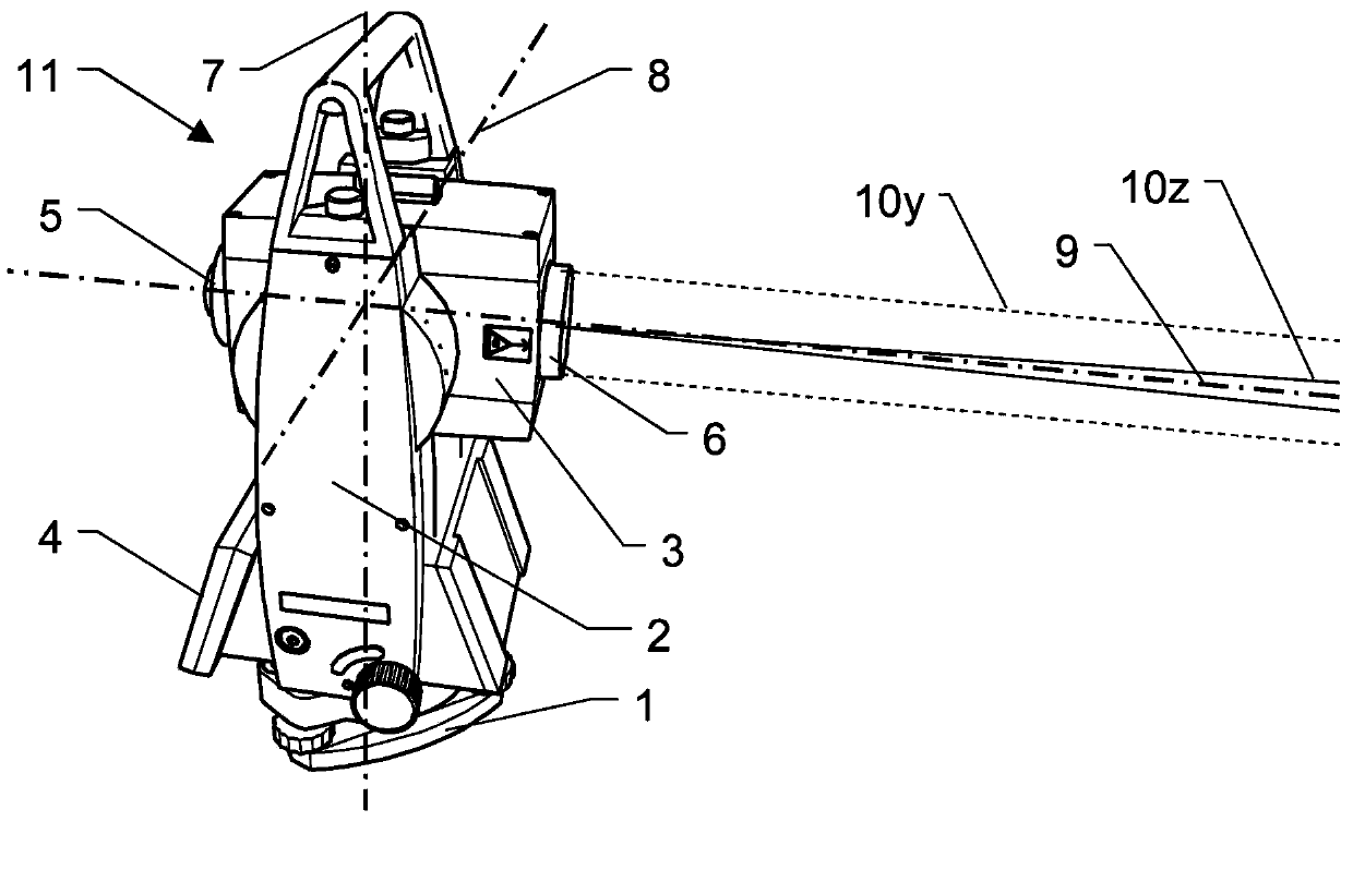
[0089] figure 1 An example of a surveying device 11 to which the present invention is applied is shown. The device 11 has a base 1 with which it is configured for surveying purposes, for example with a tripod (not shown here). Attached to the base 1 is a device body 2 of the device 11 having a vertical goniometer rotatable about a vertical axis 7 . The base 1 has a unit for horizontal alignment of the surveying device 11 or in other words for vertical adjustment of the vertical axis 7 eg by means of three adjustment screws and a circular level and / or an electronic level. The device body 2 has an operating unit 4 and is connected to the aiming unit 3 by a tilt axis goniometer, which is rotatable about a tilt axis 8 . In the case shown, the sighting unit 3 has a telescopic sight with an objective 6 and with an eyepiece 5 , ie it is equipped with a transparent light channel. Further embodiments are also possible in addition or as an alternative to the optical telescope with a ...


PUM


Abstract

The invention relates to a surveying device, a method for surveying a target object with the survey device and a computer program product. The surveying device has a base for setting up the surveying device and a targeting unit, which is rotatable in relation to the base about two axes, and which defines a target axis or targeting a target object to be surveyed. The targeting unit has a first beam path for emitting optical radiation in the direction of the target object to be surveyed and a second beam path for receiving a component of the optical radiation, which is reflected from the target object, by way of an optoelectronic receiving element. In some embodiments, at least one of the beam paths, has an optical element, which is implemented having an optically transparent, deformable volume body, and which has at least one interface toward a medium having an optical index of refraction deviating from the volume body. The interface makes the optical reflective performance changes on at least two different directions by deformation of a plurality of electrical activation signals.

Description

technical field [0001] The invention relates to an optical mapping device, in particular a tachymeter, a laser scanner, or a laser tracker, and a method for mapping a target object with an optical mapping device. Background technique [0002] The devices of surveying technology operate in various forms based on optical measuring systems. Examples of surveying devices according to this type are eg disclosed in US6,873,407, CN201892533, US2011 / 080477, EP1081459, US2012 / 127455, WO2012 / 033892, WO2007 / 079600, WO2010 / 148525 or other patents. [0003] Typically, optical radiation is emitted from these devices in the direction of the target object to be mapped, the distance and angular position of the target object, ie polar coordinates are determined, which are then usually further processed. A component of the radiation emitted from the target object to be mapped is in this case reflected to the device, received there and converted into an electrical signal for distance determina...

Claims


Application Information

Patent Timeline
IPC IPC(8): G01C15/00G01S17/02G01S17/66
CPCG02B26/004G01C15/002G02B3/14G02B26/0875G01C15/006
Inventor J·辛德林J·舍加C·L·E·迪穆兰C·艾斯利
Owner HEXAGON TECH CENT GMBH
Why Eureka
Try Eureka