Gyroscope dynamic calibration method for measuring rotary carrier transversal posture

A gyroscope and carrier technology, applied in the field of inertial sensing, can solve problems such as installation errors and failure to meet the use requirements, and achieve the effects of eliminating installation errors, reducing calibration workload, and improving measurement accuracy

Active Publication Date: 2014-10-15
CHINA ELECTRONICS TECH GRP NO 26 RES INST
View PDF4 Cites 16 Cited by
  • Summary
  • Abstract
  • Description
  • Claims
  • Application Information

AI Technical Summary

Problems solved by technology

However, when the gyroscope is installed in the rotating carrier, because the rolling axis of the gyroscope itself is required to coincide with the rotation center of the rotating carrier as much as possible, it will bring new installation errors
Since the existing calibration is completed by the manufacturer before leaving the factory, the user cannot perform calibration by himself, so it is still impossible to eliminate the error of the gyroscope installed in the rotating carrier
Since the gyroscope rotates around its own rolling axis at a high speed when working with the rotating carrier, and its speed can reach 15 r / s, the influence on the measurement of the gyro angular rate in the two directions of yaw and pitch is more obvious, so the two directions The installation error of the gyroscope relative to the rolling axis of the gyroscope needs to be eliminated accurately, and the traditional dynamic calibration method obviously cannot meet the requirements of use.

Method used


Image

  • Gyroscope dynamic calibration method for measuring rotary carrier transversal posture
  • Gyroscope dynamic calibration method for measuring rotary carrier transversal posture
  • Gyroscope dynamic calibration method for measuring rotary carrier transversal posture

Examples


Embodiment Construction

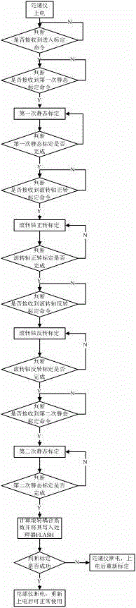
[0027] The present invention is used for the gyroscope dynamic calibration method of rotating carrier lateral attitude measurement, and the steps are as follows,

[0028] 1) Install the gyroscope in the rotating carrier first, then install the rotating carrier on the high-speed turntable, and make the rolling axis of the gyroscope perpendicular to the surface of the high-speed turntable;

[0029] 2) Then use the speed test method to identify the installation error of the gyroscope in each direction of the gyroscope relative to the rolling direction from the gyroscope error model installed inside the gyroscope and obtain the compensation coefficient, and write the compensation coefficient online to the processor inside the gyroscope In FLASH; the compensation coefficient is the preliminary calibration result;

[0030] 3) Finally, judge the correctness of the preliminary calibration result; when the preliminary calibration result is within the set compensation coefficient range,...


PUM


Abstract

The invention discloses a gyroscope dynamic calibration method for measuring rotary carrier transversal posture. The method comprises the following steps: mounting a gyroscope in a rotary carrier, mounting the rotary carrier on a high-speed rotary table, then adopting a velocity testing method to identify installation error of tops of the gyroscope in all directions corresponding to the rolling directions by a gyroscope error model so as to obtain a compensation factor, writing the compensation factor into a processor FLASH on line, and finally judging the calibration result, when the calibration result is in the set calibration result range, the calibration is effective, or calibration needs to be conducted again until the requirements are met. According to the gyroscope dynamic calibration method, not only is the installation error caused by secondary mounting eliminated, but also the primary installation error of the tops in the gyroscope is eliminated, and the gyroscope measuring accuracy is obviously improved. In calibration, the compensation factor is written into the processor FLASH inside the gyroscope on line, not only is the experiment data saved, but also the secondary code writing is avoided, and the calibration workload is greatly relieved.

Description

technical field [0001] The invention relates to dynamic calibration of gyroscopes, in particular to dynamic calibration of gyroscopes for measuring the lateral attitude of a rotating carrier, which is used to improve the accuracy and precision of gyroscope measurement, and belongs to the technical field of inertial sensing. [0002] Background technique [0003] A gyroscope is a device used to measure angular velocity. Its core component is a gyroscope. According to measurement needs, gyroscopes can be installed in several directions of yaw, roll, and pitch. Theoretically, there may be installation errors in all directions of the gyroscope, if not eliminated, it will affect the normal use of the gyroscope. In order to eliminate the installation error of the device itself and improve the measurement accuracy, the gyroscope needs to be dynamically calibrated before leaving the factory. After calibration, the finished gyroscope is sold to the user, and the user installs the g...

Claims


Application Information

Patent Timeline
Patent Type & Authority Applications(China)
IPC IPC(8): G01C25/00
CPCG01C25/00
Inventor 芶志平王瑜查安虎刘奎张彤王清亮李勇健刘勇贾晓明
Owner CHINA ELECTRONICS TECH GRP NO 26 RES INST
Why Eureka
Try Eureka