Metering a flow of a fluid through a cylindrical tube section

A technology for measuring device and fluid flow, applied in the direction of measuring device, liquid/fluid solid measurement, measuring flow/mass flow, etc. Avoid distracting and disruptive effects

Active Publication Date: 2014-10-15
NANJING YOUYANG CONTROL TECH +1
View PDF5 Cites 7 Cited by
  • Summary
  • Abstract
  • Description
  • Claims
  • Application Information

AI Technical Summary

Problems solved by technology

[0003] However, the above-mentioned patented technology has the following shortcomings: 1. A single differential pressure measurement cannot solve the error caused by the asymmetry that may occur during the processing and installation of the throttling piece; 2. The optimization of the shape of the throttling piece is not sufficient. There is room for further improvement in terms of resistance loss and flow stability; 3. Signal processing and data transmission follow the conventional method, that is, differential pressure transmitters, pressure transmitters and temperature transmitters are all outside the measuring tube. It is vulnerable to damage or influence in the external environment; 4. Due to the traditional data transmission method, the data cannot be kept confidential or is easily subject to artificial changes
[0007] In the above-mentioned patent, the fluid will generate unstable vortex when it flows through the throttling member, so that the flow measurement cannot obtain high accuracy
At the same time, due to the existence of the vortex, the impurities in the fluid will accumulate, and the throttling part does not have the self-cleaning function, which will inevitably affect the measurement
In addition, under various non-standard working conditions, due to the limitation of geometric dimensions, it is impossible to install the middle section of the cylinder with the required length, and the fluid in the pipeline causes the sharp edge wear of the throttling piece, etc., when performing fluid measurement. During the process, it is often necessary to check, clean or replace the flowmeter, which means that shut-off valves need to be installed upstream and downstream of the flowmeter, and the switching of the shut-off valve will inevitably affect the measurement accuracy.

Method used


Image

  • Metering a flow of a fluid through a cylindrical tube section
  • Metering a flow of a fluid through a cylindrical tube section
  • Metering a flow of a fluid through a cylindrical tube section

Examples


Embodiment

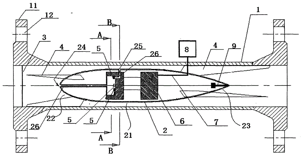
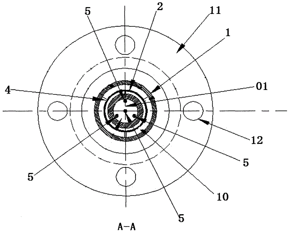
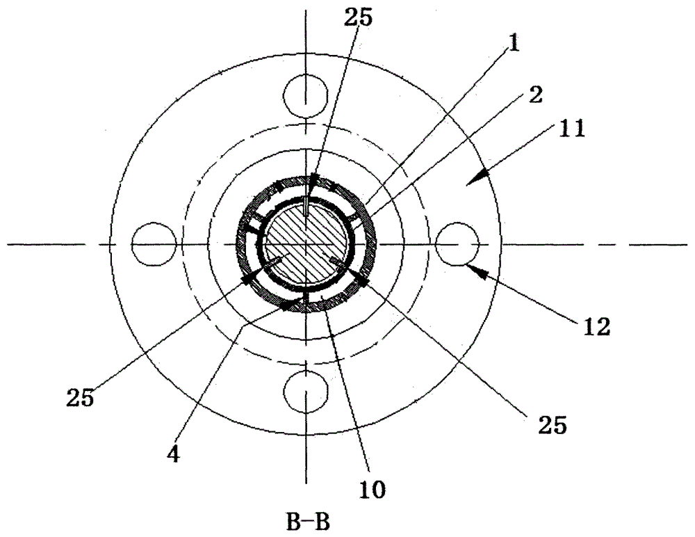
[0037] Figure 1 to Figure 3 In the shown embodiment, the two ends of the measuring tube 1 are sealed and welded with flanges 11 respectively, and the flange 11 has bolt holes 12. When measuring, the device of the present invention can be connected to the device through the bolt holes 12 on the flange 11. It is connected to the pipeline to be tested, and makes the front end 22 of the throttling part 2 face the direction of fluid flow. An annular fluid channel is formed between the cylindrical middle section 21 of the throttling part 2 of the streamline body and the inner wall of the measuring tube 1 . The filter screen 3 can play the effect of preventing impurities from accumulating and blocking.

[0038] The front end 22 of the throttling member 2 is ellipsoidal, and the rear end 23 is curved and conical, which can be more effective in avoiding the generation of fluid vortices, and facilitate the setting of more favorable pressure extraction points to obtain more accurate pr...


PUM


Abstract

The invention discloses a fluid flow metering apparatus which comprises a metering pipe, a throttling element, a support element and a signal processing unit. The throttling element is a streamline body and has a cylindrical tube section with equal diameters. The throttling element is fixed inside the metering pipe through the support element and coaxial to the metering pipe. An annular flow channel is formed between the cylindrical tube section of the throttling element and the metering pipe. The front of the throttling element is provided with high-pressure taps. Low pressure taps are arranged inside the annular flow channel. At least one low pressure tap is located on the outer wall of the throttling element. The signal processing unit comprises a signal processor, a pressure difference sensor and at least two pressure sensors. The signal processing unit is used for acquiring the pressure difference among the high pressure taps and the low pressure taps, or respectively acquiring the pressure values of the low pressure taps and the high pressure taps so as to transmit the values to a signal processor. The signal processor calculates the flow of a fluid according to the received pressure difference or the pressure signals. The metering results are more accurate. Interference and damage during a data transmission process can be further prevented.

Description

technical field [0001] The invention relates to the technical field of fluid flow measurement, in particular to a fluid flow measurement device. Background technique [0002] In the prior art, the patent CN2736741 discloses a differential pressure flowmeter. The flow measurement system includes a roughly drop-shaped throttling piece, and measures The pipe wall is connected; the throttling piece is coaxial with the measuring tube, and there is a cylindrical straight pipe section in the middle; thus, an equal-width annular flow channel is formed between the straight pipe section of the throttling piece and the inner wall of the measuring tube, and the fluid flows in the When flowing through the annular flow channel under the action of internal pressure, the speed will increase and the flow will be adjusted to a very stable state. This flow regime is manifested without any flow separation or vortices at the front, middle and rear of the throttle. [0003] However, the above-m...

Claims


Application Information

Patent Timeline
Patent Type & Authority Applications(China)
IPC IPC(8): G01F1/34
CPCG01F1/40G01F1/46G01F1/363
Inventor 明晓于尔根·康朋汉斯
Owner NANJING YOUYANG CONTROL TECH
Why Eureka
Try Eureka