A method and device for testing the lateral stiffness of a tubular belt
A technology of lateral stiffness and test device, applied in the field of testing, can solve the problems of deviation of test results from actual values, limitation of use range, deviation of data, etc.
- Summary
- Abstract
- Description
- Claims
- Application Information
AI Technical Summary
Problems solved by technology
Method used
Image
Examples
Embodiment 1
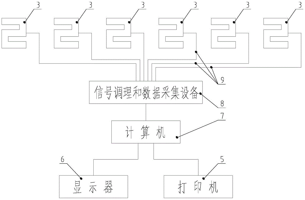
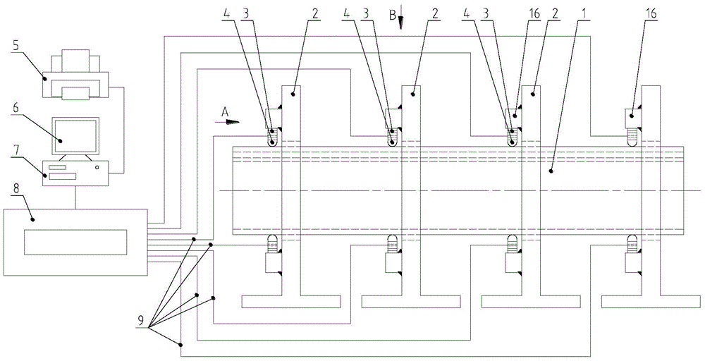
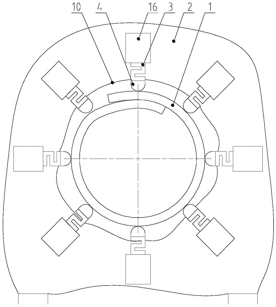
[0067] like figure 2 , image 3 and Figure 4 As shown, the test device for transverse stiffness of the tubular belt in this embodiment is composed of four sets of test heads 4, corresponding four sets of sensors 3, and four panels 2, and each set of test heads 4 is arranged in a circle around the horizontal axis of the center of the panel 2 along the circumferential direction. Shape, the test head 4 is connected with the sensor 3, and the sensor 3 is connected with the panel 2 through the connecting piece 16. The test sample block 1 is circled into a circular tube shape and placed in the circular tube-shaped space surrounded by four sets of test heads 4 . Due to the existence of tension, the test sample block 1 has a certain pressure on the test head, which can be detected by the sensor 3 . like figure 1 and figure 2 As shown, the wire 9 of the sensor 3 is connected to the signal conditioning and data acquisition device 8, and the processed signal is sent to the compute...
Embodiment 2
[0071] like Image 6 and Figure 7As shown, the present embodiment is made up of base 18, three panels 2, idler 17, sensor 3, slide bar 15, slide seat 13, lead screw 12, nut seat 14, slide seat 13 is fixed on panel 2, slide bar 15 and the sliding seat 13 form a sliding pair, one end of the slide bar 15 is connected with a coupling 16, the sensor 3 is connected with the coupling 16, and the idler 17 is connected with the sensor 3. The nut seat 14 is fixed on the panel 2, the nut seat 14 has internal threads, the lead screw 12 has external threads, and the nut seat 14 forms a thread pair, the lead screw 12 and the connecting piece 16 form a rotating pair 39, and the lead screw 12 is connected There is a handwheel 11, and the lead screw 12 is in the same direction as the slide rod 15. Rotating the handwheel 11 can drive the coupling 16, the sensor 3 and the supporting roller 17 to move toward or away from the direction of the test sample block 1.
[0072] like Figure 7 As sho...
Embodiment 3
[0079] like Figure 8 and Figure 9 As shown, the moving pair connected with the coupling 16 is a guide rod-guide sleeve structure, a guide sleeve 29 is installed on the coupling 16, the guide rod 28 is connected with the guide rod seat 27, the guide rod seat 27 is connected with the panel 2, and the guide rod The direction of 28 is parallel with leading screw 12, and turning hand wheel 11 can drive coupling 16, sensor 3 and supporting roller 17 equally.
[0080] A set of idlers 17, sensors 3, guide rods 28, guide seats 27, lead screws 12, nut seats 14, pointers 32 and scales 33 that work in coordination with each other are alternately arranged on both sides of the panel. Figure 9 Components depicted by dotted lines are on the back of the panel, and components depicted by solid lines are on the front. In this way, the working condition of rollers arranged alternately on both sides of the panel can be simulated, and the measured data is closer to the real value.
[0081] A ...
PUM
 Abstract
Description
Claims
Application Information
 - R&D
- Intellectual Property
- Life Sciences
- Materials
- Tech Scout
- Unparalleled Data Quality
- Higher Quality Content
- 60% Fewer Hallucinations
Browse by: Latest US Patents, China's latest patents, Technical Efficacy Thesaurus, Application Domain, Technology Topic, Popular Technical Reports.
© 2025 PatSnap. All rights reserved.Legal|Privacy policy|Modern Slavery Act Transparency Statement|Sitemap|About US| Contact US: help@patsnap.com


