Low voltage load test device

A technology for testing devices and low-voltage loads, applied in measuring devices, measuring electricity, measuring electrical variables, etc., can solve problems such as easy electric shock burns, safety accidents, high risks, etc., and achieve reliable production quality, high production efficiency, and low production costs Effect

Inactive Publication Date: 2014-10-15
STATE GRID CORP OF CHINA +1
View PDF6 Cites 2 Cited by
  • Summary
  • Abstract
  • Description
  • Claims
  • Application Information

AI Technical Summary

Problems solved by technology

In recent years, with the expansion of the urban framework, the power consumption of various industries has increased sharply, and the distribution transformers have also gradually increased. , under the supervision of one person, the surveyor needs to clim

Method used


Image

  • Low voltage load test device

Examples


Embodiment Construction

[0015] The technical solutions of the present invention will be described in further detail below through specific implementation methods.

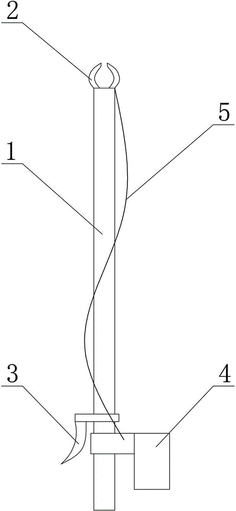
[0016] Such as figure 1 Shown, a kind of low-voltage load test device comprises a 2-meter-long insulating rod 1, a clamp-type current transformer 2 arranged at the top of the insulating rod, an ammeter 4 arranged at the lower end of the insulating rod 1, and an ammeter 4 arranged at the insulating rod 1. The handbrake 3 at the lower end, the handbrake 3 is connected to the clamp current transformer 2 to control its opening and closing through the handbrake line, and the clamp current transformer 2 is connected to the ammeter 4 through the current secondary line 5, and the clamp current transformer 2 is connected to the current secondary line 5. The transformer 2 and the ammeter 4 are respectively the clamp current transformer part and the ammeter part of the clamp ammeter.

[0017] When working, the operator holds the lower end of the in...


PUM


Abstract

The invention provides a low voltage load test device. The low voltage load test device comprises an insulating rod, a clamp-shaped current transformer which is arranged at the top of the insulating rod, an ammeter which is arranged on the lower end of the insulating rod, and a handbrake which is arranged on the lower end of the insulating rod. The handbrake is connected with the clamp-shaped current transformer through a handbrake line to control the clamp-shaped current transformer to switch on and off. The clamp-shaped current transformer is connected with the ammeter through a current secondary line. The low voltage load test device has the advantages of scientific design, high work efficiency and high safety coefficient.

Description

technical field [0001] The invention relates to a test device, in particular to a low-voltage load test device. Background technique [0002] The low-voltage load test of distribution transformers is an essential and important task every day, and each transformer should be tested 2-3 times a day. In recent years, with the expansion of the urban framework, the electricity consumption of various industries has increased sharply, and the distribution transformers have also gradually increased. , under the supervision of one person, the surveyor needs to climb on the 3.5-meter-high live distribution transformer bench for operation, which is risky, close contact with wires, easy to get electric shock and burns, and climbing up and down, it takes a very long time and a long time of labor Very prone to safety accidents. [0003] In order to solve the above existing problems, people have been seeking an ideal technical solution. Contents of the invention [0004] The object of ...

Claims


Application Information

Patent Timeline
IPC IPC(8): G01R31/00
Inventor 于溪波
Owner STATE GRID CORP OF CHINA
Why Eureka
Try Eureka