
Cell architecture, layout, working method and device

A cell and anchor cell technology, applied in the network field, can solve the problems of terminal service interruption, inability to meet the continuous access of the terminal, and taking a long time to achieve the effect of saving energy consumption, avoiding interruption, and satisfying continuous access.

Inactive Publication Date: 2014-10-15
CHINA MOBILE COMM GRP CO LTD
View PDF3 Cites 8 Cited by
  • Summary
  • Abstract
  • Description
  • Claims
  • Application Information

AI Technical Summary

Problems solved by technology

[0006] However, when a terminal enters the coverage area of ​​a dormant small cell base station, the terminal needs to first detect the dormant small cell base station, and then activate it. These two processes will take a long time. As a result, the service of the terminal may be interrupted, that is, the continuous access of the terminal cannot be satisfied.

Method used


Image

  • Cell architecture, layout, working method and device
  • Cell architecture, layout, working method and device
  • Cell architecture, layout, working method and device

Examples


example 1

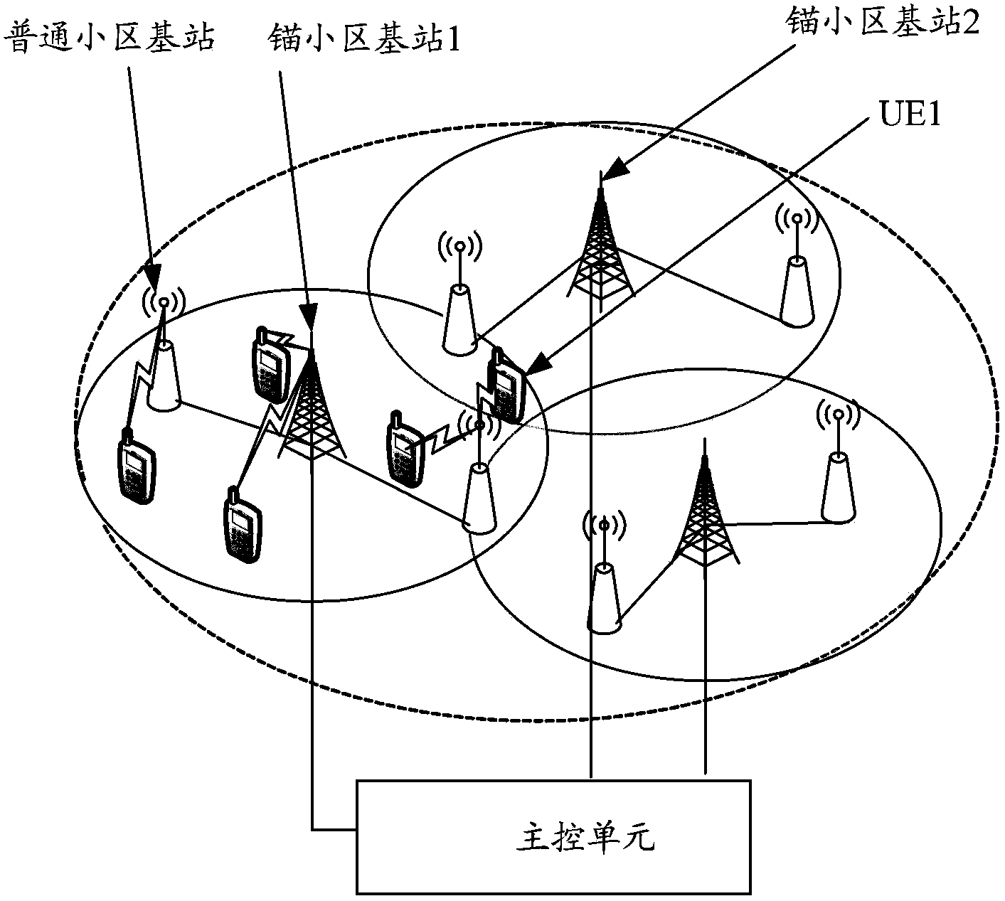
[0114] image 3 It is a schematic diagram of the terminal initial access method in Example 1 of the present invention; Figure 4 It is a schematic diagram of the final access mode of the terminal in Example 1 of the present invention.

[0115] A. If image 3 As shown, the anchor cell base station 1 and its subordinate common cell base stations serve many terminals, and the load is relatively large;

[0116] By obtaining the load information of each anchor cell base station and the ordinary cell base stations subordinate to each anchor cell base station, the main control unit learns that the anchor cell base station 1 and its subordinate ordinary cell base stations have relatively large loads, and the anchor cell base station 1 adjacent to the anchor cell base station The load of the anchor cell base station 2 is relatively small;

[0117] B. If Figure 4 As shown, the main control unit performs load balancing among cell base stations, and switches UE1 to anchor cell base s...

example 2

[0119] Figure 5 It is a schematic diagram of the terminal initial access method in Example 2 of the present invention; Image 6 It is a schematic diagram of the final access mode of the terminal in Example 2 of the present invention.

[0120] A. If Figure 5 As shown, UE1 and UE2 are respectively connected to two different common cell base stations under the management of anchor cell base station 1 and anchor cell base station 2;

[0121] UE1 and UE2 are scheduled to the same resource block (RB, Resource Block), so there is serious co-channel interference;

[0122] B. If Image 6 As shown, the main control unit learns the existing interference by obtaining the interference information on each carrier of each anchor cell base station and the common cell base station subordinate to each anchor cell base station, and performs interference coordination between the cell base stations; respectively UE1 and UE2 Scheduling to different RBs, thereby reducing or even eliminating in...


PUM


Abstract

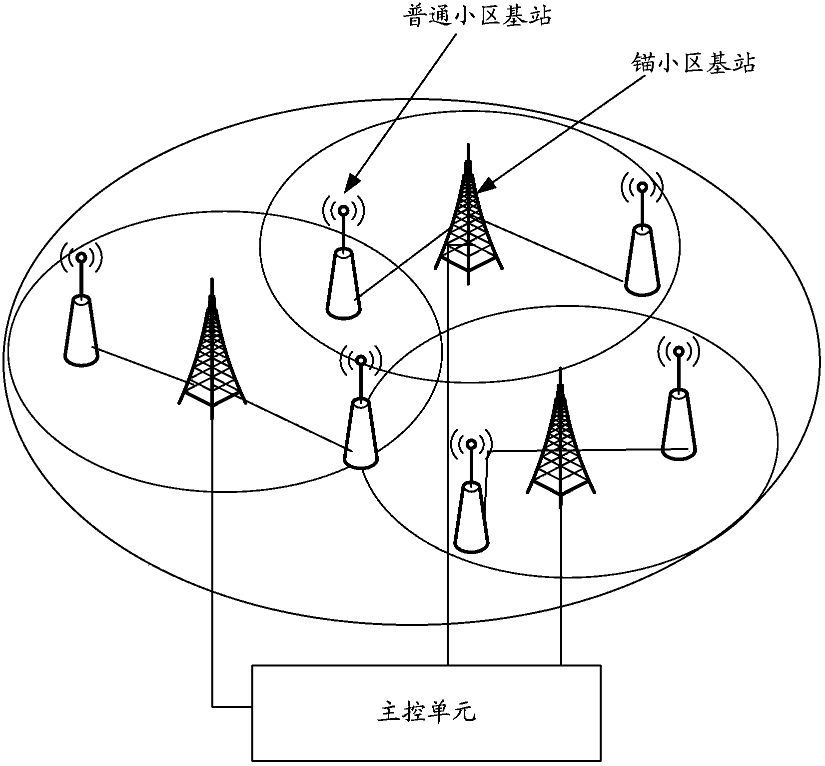
The invention discloses a cell architecture, a layout, a working method and a device. The cells of each cell cluster are divided into two types which are anchor cells and common cells, wherein each anchor cell belongs to at least one common cell and each common cell belongs to an anchor cell; each cell cluster corresponds to a main control unit for controlling all anchor cell base station in the cell cluster and controlling all common cell base station through all anchor cell base station in the cell cluster; the anchor base stations are always in an activation state for guaranteeing the constant coverage of the cell cluster where the anchor cell base stations are in and are used for performing information transferring between main control units in the cell cluster and the all subordinate common cell base stations; and the common base stations are used for being in an activation state or in a dormancy state under the control of the main control unit in the cell cluster. By implementing the scheme of the invention, the energy consumption can be saved and the constant access of the terminal can be guaranteed.

Description

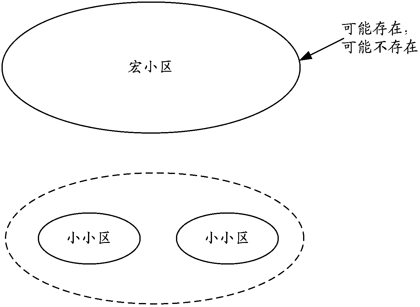
technical field [0001] The present invention relates to network technology, in particular to a cell structure and its layout and working method and device. Background technique [0002] In order to further improve spectrum efficiency or supplement blindness and heat, the industry proposes a small cell application scenario, that is, to deploy small cells within the coverage area of ​​the original macro cell or in the coverage blind spot of the macro cell. [0003] figure 1 It is a schematic diagram of a deployment mode of an existing small cell. Such as figure 1 As shown, the macro cell may or may not exist. [0004] Due to the small coverage area of ​​a small cell, a large number of sites usually need to be deployed. In this way, if all the small cell base stations are always in the active state (or referred to as the on state), it will require a lot of energy consumption. [0005] For this reason, it is proposed in the prior art that the small cell base station can ent...

Claims


Application Information

Patent Timeline
Patent Type & Authority Applications(China)
IPC IPC(8): H04W52/02H04W76/00
CPCY02D30/70
Inventor 刘宇超沈晓冬金婧胡臻平
Owner CHINA MOBILE COMM GRP CO LTD
Learn More