Phase discontinuity tester for multi antenna transmitters sending phase perturbed signals

A continuity and tester technology, applied in diversity/multi-antenna systems, transmitter monitoring, space transmit diversity, etc., can solve problems such as net phase discontinuity

Inactive Publication Date: 2014-10-15
GOOGLE LLC
View PDF2 Cites 2 Cited by
  • Summary
  • Abstract
  • Description
  • Claims
  • Application Information

AI Technical Summary

Problems solved by technology

In reality, however, the net phase discontinuity of the two signals sensed at the receiver is often non-zero due to various effects occurring in the transmitter, and the user equipment must perform test

Method used


Image

  • Phase discontinuity tester for multi antenna transmitters sending phase perturbed signals
  • Phase discontinuity tester for multi antenna transmitters sending phase perturbed signals
  • Phase discontinuity tester for multi antenna transmitters sending phase perturbed signals

Examples


Embodiment Construction

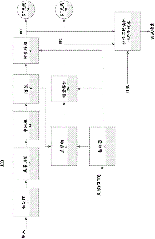
[0015] figure 1 A block diagram is shown illustrating one example of a communication device 100 and associated test equipment. Device 100 may eg be a mobile phone. The device comprises a pre-processing stage 10 which receives the input signal to be transmitted and performs various operations on this signal. For example, input signals from different channels may be combined using one or more multiplexing techniques (eg, TDM, FDM, CDM, PDM, etc.). Furthermore, the input signal may be encoded for error detection and / or may be encrypted so that it cannot be read by unauthorized parties. Other types of processing may also be performed at stage 10 . The preprocessed signal may be a digital signal which is then modulated by the baseband modulation stage 12 . One or more intermediate stages 14 are then used to process the modulated signal from stage 12 in the baseband frequency range or in the intermediate frequency range. Next, RF stage 16 converts the output of stage 14 to the...


PUM


Abstract

A tester for determining phase discontinuity is described for a transmitter having multiple antennas sending signals to a receiver. Typically the transmitter is provided in a mobile telephone and the receiver is in a base station. The transmitter sends out the RF signals in a shaped beam using transmission diversity. The RF signals define multiplexing slots. The tester receives the RF signals as they are fed to a respective antenna port, analyses phases of these signals on a slot-by-slot basis comparing phase differences between adjacent slots to a threshold derived from legacy devices.

Description

[0001] Cross References to Related Applications [0002] This application claims priority to US Provisional Patent Application No. 61 / 597,015, filed February 9, 2012, which is hereby incorporated by reference in its entirety. technical field [0003] The present disclosure relates generally to the field of wireless communications and more particularly to a tester for detecting phase discontinuities in phase perturbation signals from multi-antenna transmitters. Background technique [0004] A modifying communication device, such as a user equipment UE, has a transmitter comprising a plurality of antenna elements that transmit signals for conveying information. A receiving communication device (typically located at a base station) extracts information from the transmitted signal. Multiple antenna elements enhance spectral efficiency, allowing more users to be served simultaneously on a given frequency band. However, the transmit signal travels along a different path and may...

Claims


Application Information

Patent Timeline
Patent Type & Authority Applications(China)
IPC IPC(8): H04B17/00H04B7/06
CPCH04B17/0025H04B17/0027H04B17/19H04B17/0017H04B17/17H04B7/0617H04B17/15H04B17/18H04B17/0022H04B7/06
Inventor S·王
Owner GOOGLE LLC
Why Eureka
Try Eureka