adjustable ejector

The technology of flow device and jet box is applied in the field of suction and negative pressure equipment, which can solve the problems of low nozzle bearing pressure, unadjustable nozzle, twisted orifice, etc., and achieves the effect of good cleaning performance, simplified structure, and improved bearing pressure.

Active Publication Date: 2016-05-04
GP ENTERPRISES CO LTD
View PDF1 Cites 0 Cited by
  • Summary
  • Abstract
  • Description
  • Claims
  • Application Information

AI Technical Summary

Problems solved by technology

[0003] For the nozzles in the existing ejector, if the nozzles are clogged, use a soft brush or toothpick to clean it and be very careful during the cleaning process, which may distort the orifice. In addition, the existing nozzles have low bearing pressure and low efficiency. At the same time, The spout is not adjustable

Method used


Image

  • adjustable ejector

Examples


Embodiment

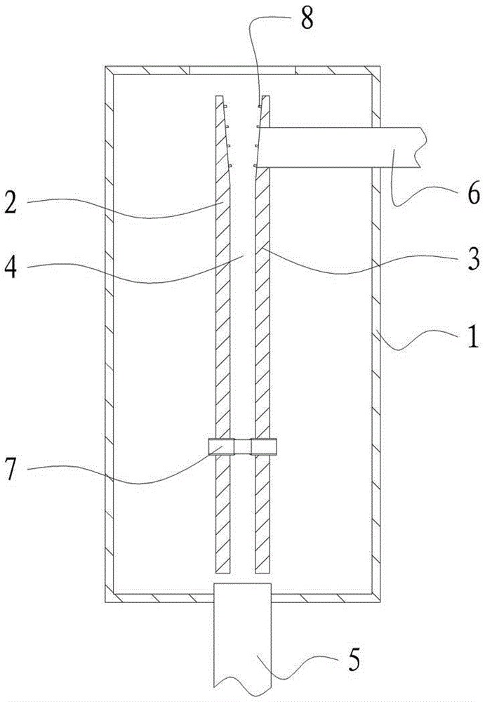
[0016] The adjustable ejector of the present embodiment, such as figure 1 As shown, it includes a jet box 1 provided with an outlet, and the jet box 1 is provided with a relative left splint 2 and a right splint 3, and a jet nozzle 4 is formed between the left splint 2 and the right splint 3, and the left splint 2 and the right splint 3 The distance is 8-20mm, the outlet end of the jet nozzle 4 is set opposite to the outlet of the jet box 1,

[0017] The inlet end of the jet nozzle 4 is provided with a jet liquid inlet pipe 5, the jet liquid inlet pipe 5 is parallel to the left splint 2 and the right splint 3, the inlet of the jet liquid inlet pipe 5 is connected with the outside of the jet box 1, and the edge of the right splint 3 is provided with a The air inlet pipe 6 connected to the outlet end of the jet nozzle 4 . Bolts 7 are perforated between the left splint 2 and the right splint 3, and the two ends of the bolts 7 are respectively screwed to the left splint 2 and the...


PUM


Abstract

The invention relates to an adjustable jet device and belongs to the technical field of jet pumps utilizing inertia of pumped fluid to pump fluid. The jet device comprises a jet box with an outlet, a left clamp plate and a right clamp plate are oppositely arranged in the jet box, a jet nozzle is formed between the left clamp plate and the right clamp plate which are spaced by 8-20mm, an outlet end of the jet nozzle is arranged opposite to the outlet of the jet box, a jet fluid inlet tube is arranged at an inlet end of the jet nozzle and is parallel to the left clamp plate and the right clamp plate, an inlet of the jet fluid inlet tube is communicated with the exterior of the jet box, an air inlet tube communicated with the outlet end of the jet nozzle is arranged at an edge of the right clamp plate, a bolt is penetratingly arranged between the left clamp plate and the right clamp plate, and two ends of the bolt are in screw joint with the left clamp plate and the right clamp plate respectively and extend out of the left clamp plate and the right clamp plate in suspension respectively. The adjustable jet device has the advantages of high pressure-bearing capacity, good cleaning performance and adjustability in size of the jet nozzle.

Description

technical field [0001] The invention relates to a negative pressure suction device, which belongs to the technical field of jet pumps for pumping fluid by utilizing the inertia of the pumped fluid. Background technique [0002] Jet vacuum pump is a device that generates, improves and maintains vacuum in a closed space by mechanical, physical, chemical or physical and chemical methods. It is generally composed of three parts: submersible pump, ejector, and pump box. It is widely used in decompression evaporation, crystallization, distillation, drying, decolorization, deodorization, vacuum transportation, etc. in petroleum, chemical, food, pharmaceutical, light industry, environmental protection and other industries. In the process. [0003] For the nozzles in the existing ejector, if the nozzles are clogged, use a soft brush or toothpick to clean it and be very careful during the cleaning process, which may distort the orifice. In addition, the existing nozzles have low bear...

Claims


Application Information

Patent Timeline
Patent Type & Authority Patents(China)
IPC IPC(8): F04F5/04
Inventor 周长根候潇寒张薇华陆俊芳
Owner GP ENTERPRISES CO LTD
Why Eureka
Try Eureka