

Sealing structure for rotary shaft of flue gas valve
A shaft sealing and valve technology, applied in shaft sealing, engine sealing, valve details, etc., can solve problems such as shaft end leakage, and achieve the effect of small instantaneous impact force, good convenience, and improved convenience.
Active Publication Date: 2014-10-22
江苏明江阀业有限公司
View PDF10 Cites 12 Cited by
- Summary
- Abstract
- Description
- Claims
- Application Information
AI Technical Summary
Problems solved by technology
Method used
View moreImage
Smart ImageViewing Examples

Examples
Embodiment 2
[0033] Embodiment 2 is different from Embodiment 1 in that: the area of the high temperature end of the thermoelectric tube is 80% of the area of the door panel.
Login to View More PUM
 Abstract
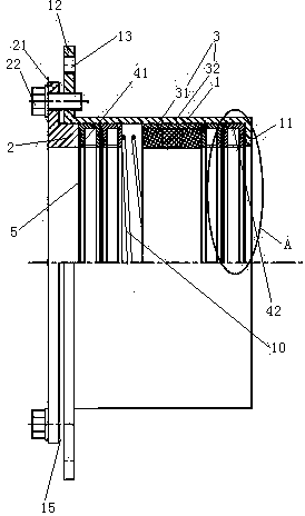
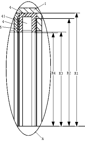
The invention relates to a flue gas valve, and discloses a sealing structure for a rotary shaft of a flue gas valve. The sealing structure comprises a packing pipe. A pressing ring, first buffering rings, a compression spring, a graphite sealing ring and second buffering rings which are sequentially butted to one another are arranged in the packing pipe, an inner rib is arranged at one end of the packing pipe, an outer rib is arranged at the other end of the packing pipe, an outer flange is arranged at the end, which is far away from the first buffering rings, of the pressing ring and is connected with the outer rib by assembling bolts, an adjusting gap is reserved between the outer flange and the outer rib, the second buffering rings are butted to the inner rib, the outer peripheral surface of the graphite sealing ring is hermetically connected with the inner peripheral surface of the packing pipe, the flue gas valve comprises the rotary shaft, the rotary shaft is penetratingly arranged in the graphite sealing ring and is hermetically butted to the graphite sealing ring, matching surfaces of the rotary shaft and the graphite sealing ring are conical surfaces, and small-diameter ends of the conical surfaces are close to the inner rib. The sealing structure for the rotary shaft of the flue gas valve has the advantages that a shaft end of the rotary shaft of the flue gas valve can be sealed by the sealing structure, and sealing effects can be adjusted; the problem of leakage at a shaft end of an existing flue gas valve can be solved by the aid of the sealing structure.
Description
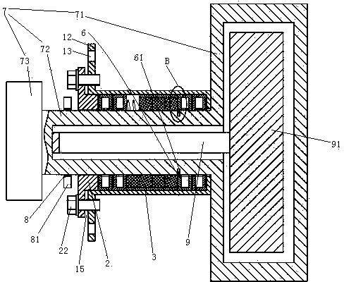
technical field [0001] The invention relates to a flue gas valve, in particular to a shaft sealing structure of the flue gas valve, which belongs to the technical field of gas turbine power generation. Background technique [0002] The flue gas valve is a device connected to a gas turbine (also known as a gas turbine) and a waste heat boiler. The temperature of the flue gas inside is between 500 ° C and 700 ° C, and the pressure is 5000 ~ 6500 Pa. When used, it is driven by an external hydraulic cylinder or a motor. Drive the shaft of the flue gas valve to rotate, so as to realize the rotation of the valve plate from 0 to 90°. A flue gas valve and a sealing structure are disclosed in a patent document with a Chinese application number of 2007101646590, a publication date of July 9, 2008, and a title of "smoke baffle door and sealing device". The existing flue gas valves only solve the sealing problem when the valve plate and the flue are closed, and the sealing between ...
Claims
Login to View More Application Information
Patent Timeline
 IPC IPC(8): F16J15/16F16K41/02
Inventor 危金兰
Owner 江苏明江阀业有限公司