Indicator lamp and light emitting device thereof

A technology for light-emitting devices and indicator lights, which is applied to electric light sources, light source fixing, and components of lighting devices, etc., can solve the problems of complicated assembly procedures, large amount of epoxy glue, and incompatibility with assembly processes, and simplify production and assembly. process, the effect of meeting the requirements of mass production

Active Publication Date: 2014-10-22
SUZHOU SIEMENS ELECTRIC APPLIANCE
View PDF5 Cites 1 Cited by
  • Summary
  • Abstract
  • Description
  • Claims
  • Application Information

AI Technical Summary

Problems solved by technology

[0003] However, as the batch production of indicator lights gradually develops toward automation, since the circuit board assembly 12 of the light emitting device 10 is circular and needs to be packaged and fixed on the base body 11 by epoxy glue, the amount of epoxy glue used is large, resulting in production

Method used


Image

  • Indicator lamp and light emitting device thereof
  • Indicator lamp and light emitting device thereof
  • Indicator lamp and light emitting device thereof

Examples


Embodiment Construction

[0036] In order to make the technical problems, technical solutions and beneficial effects to be solved by the present invention clearer, the present invention will be further described in detail below in conjunction with the accompanying drawings and embodiments. It should be understood that the specific embodiments described here are only used to explain the present invention, not to limit the present invention.

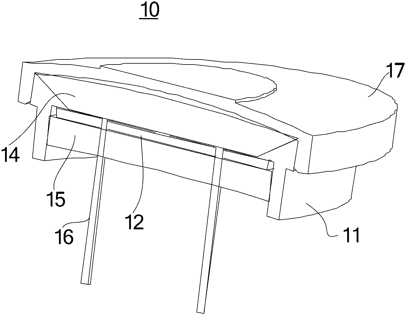
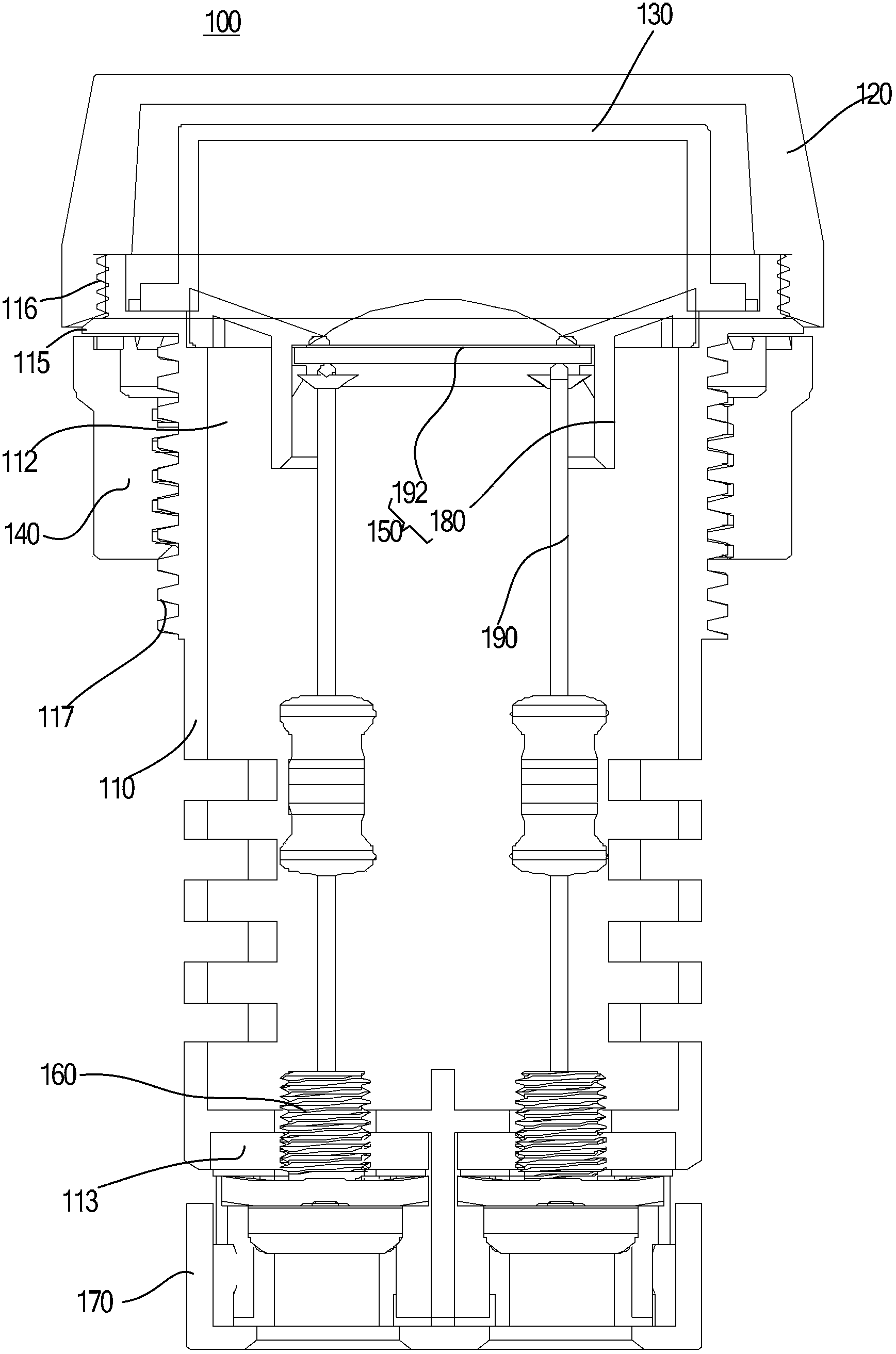
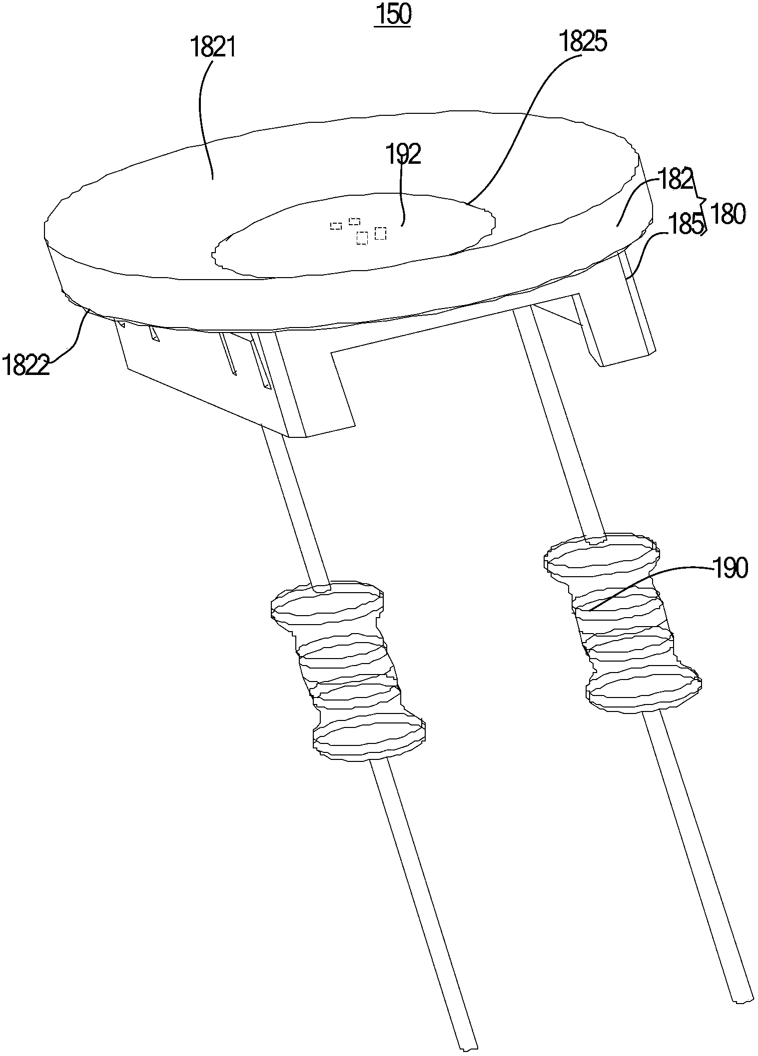
[0037] figure 2 Shown is a schematic diagram of an indicator light 100 in an embodiment of the present invention. Such as figure 2 As shown in , the indicator light 100 includes a housing 110, a lampshade 120, a lining 130, a nut 140, a light emitting device 150, at least one such as two step-down electronic components 190, two terminals 160 and a end cap 170 .

[0038] Specifically, the casing 110 is substantially cylindrical and has a first end 112 and a second end 113 . The first end 112 and the second end 113 are opposite ends of the housing 110 . A step...


PUM


Abstract

The invention discloses a light emitting device which comprises a seat and a circuit board. The rectangular circuit board is mounted on the seat in a fastened manner. An embodiment of the invention further provides an indicator lamp which comprises the light emitting device. The indicator lamp and the light emitting device have the advantages that the circuit board of the light emitting device is mounted on the seat in the fastened manner, a worker only needs to directly fastening the assembled circuit board onto the seat, accordingly, fixing effects can be realized, manufacturing and assembling processes can be simplified, and requirements of automatic large-scale production can be met.

Description

technical field [0001] The invention relates to an indicator light and a light emitting device thereof. Background technique [0002] figure 1 Shown is a schematic diagram of a light emitting device 10 of an indicator light in the prior art. Such as figure 1 As shown in , the light-emitting device 10 includes an annular seat body 11, a circular circuit board assembly 12, a first epoxy colloid layer 14, a second epoxy colloid layer 15, two pins 16 and a seat body cap17. During the assembly process of the light-emitting device 10, the annular seat 11 and the seat cap 17 are first assembled together, and then epoxy glue is filled into the assembled annular seat 11 and the seat cap 17; then, the circuit The board assembly 12 and the pins 16 installed on the circuit board assembly 12 are placed on the steps of the annular seat body 11, and the flattening operation is carried out after vacuuming. After the epoxy glue is cured, a second An epoxy colloid layer 14 and a second e...

Claims


Application Information

Patent Timeline
IPC IPC(8): F21S2/00F21V17/10F21V17/12F21V23/00
Inventor 邱东平吴红飞张顺斌
Owner SUZHOU SIEMENS ELECTRIC APPLIANCE
Why Eureka
Try Eureka