
Collection ring carbon brush holder

A collector ring and carbon brush holder technology, applied in current collectors, rotary current collectors, circuits, etc., can solve problems such as affecting motor operation, inability to provide electrical conductivity, and elastic fatigue.

Inactive Publication Date: 2014-10-22
TAIWAN LONG HAWN ENTERPRISES
View PDF5 Cites 4 Cited by
  • Summary
  • Abstract
  • Description
  • Claims
  • Application Information

AI Technical Summary

Problems solved by technology

However, the elastic pushing method of the torsion spring will produce uneven force due to the single-point push of the torsion spring, so that the carbon brush is prone to uneven wear and tear after a period of use due to elastic fatigue. Lead to poor contact between the carbon brush and the collector ring, which cannot provide good electrical conductivity and affect the operation of the motor

Method used


Image

  • Collection ring carbon brush holder
  • Collection ring carbon brush holder
  • Collection ring carbon brush holder

Examples


Embodiment Construction

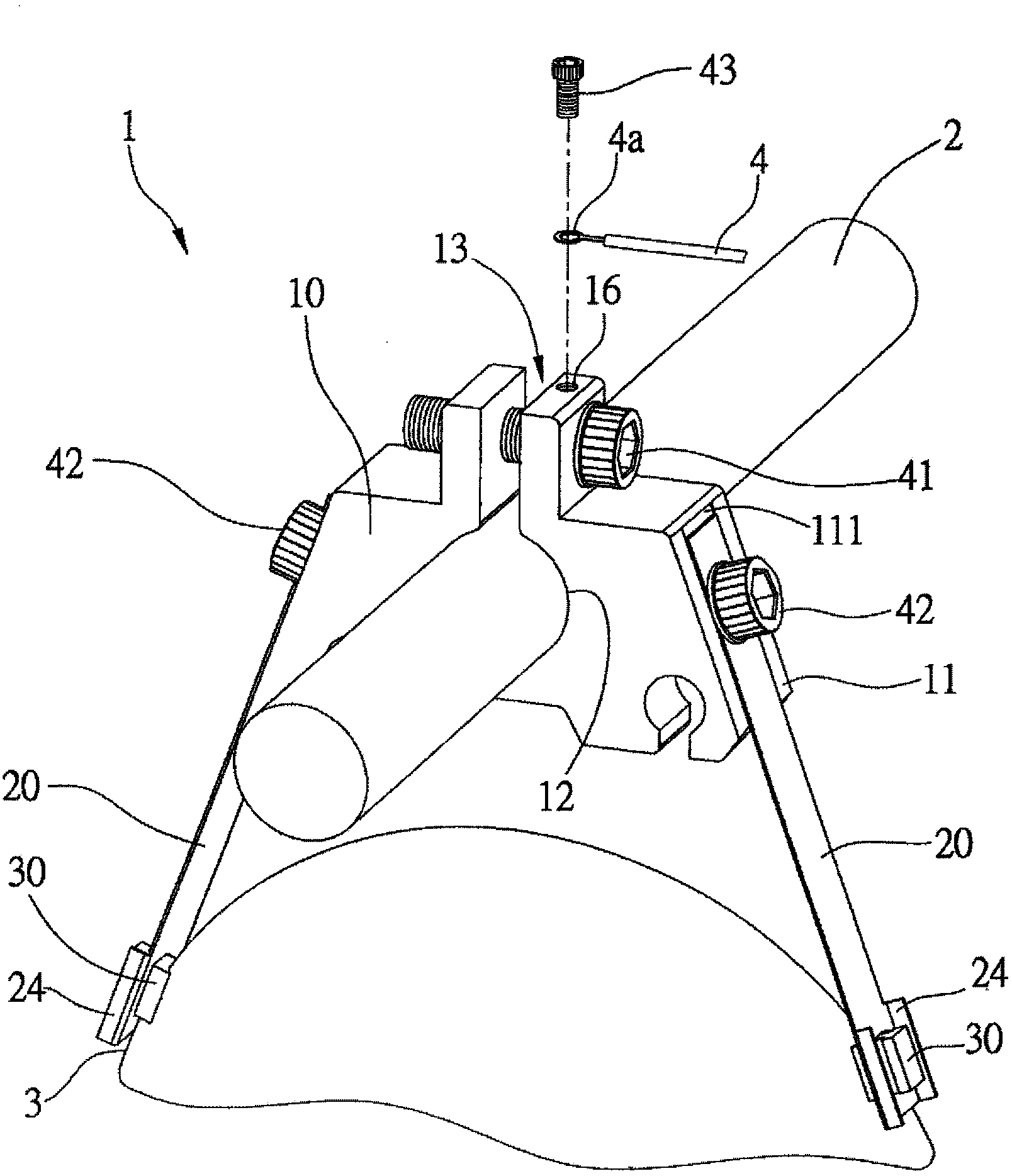
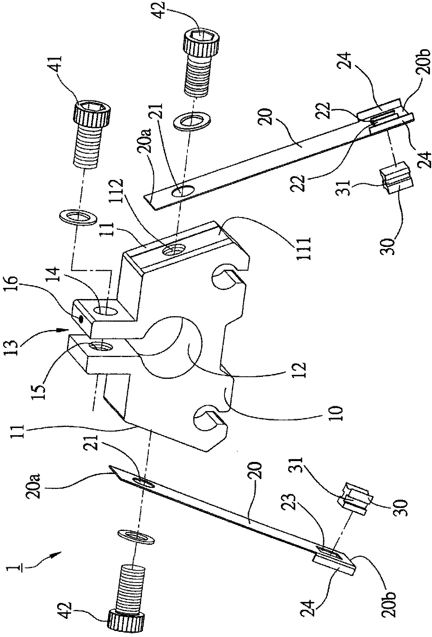
[0014] In order to illustrate the present invention more clearly, a preferred embodiment is given and detailed description is as follows in conjunction with the drawings, please refer to figure 1 and figure 2 As shown, the slip ring carbon brush holder 1 of a preferred embodiment of the present invention is located between a fixed shaft 2 and a slip ring 3 , and includes a joint seat 10 , two brackets 20 and two carbon brushes 30 . in:

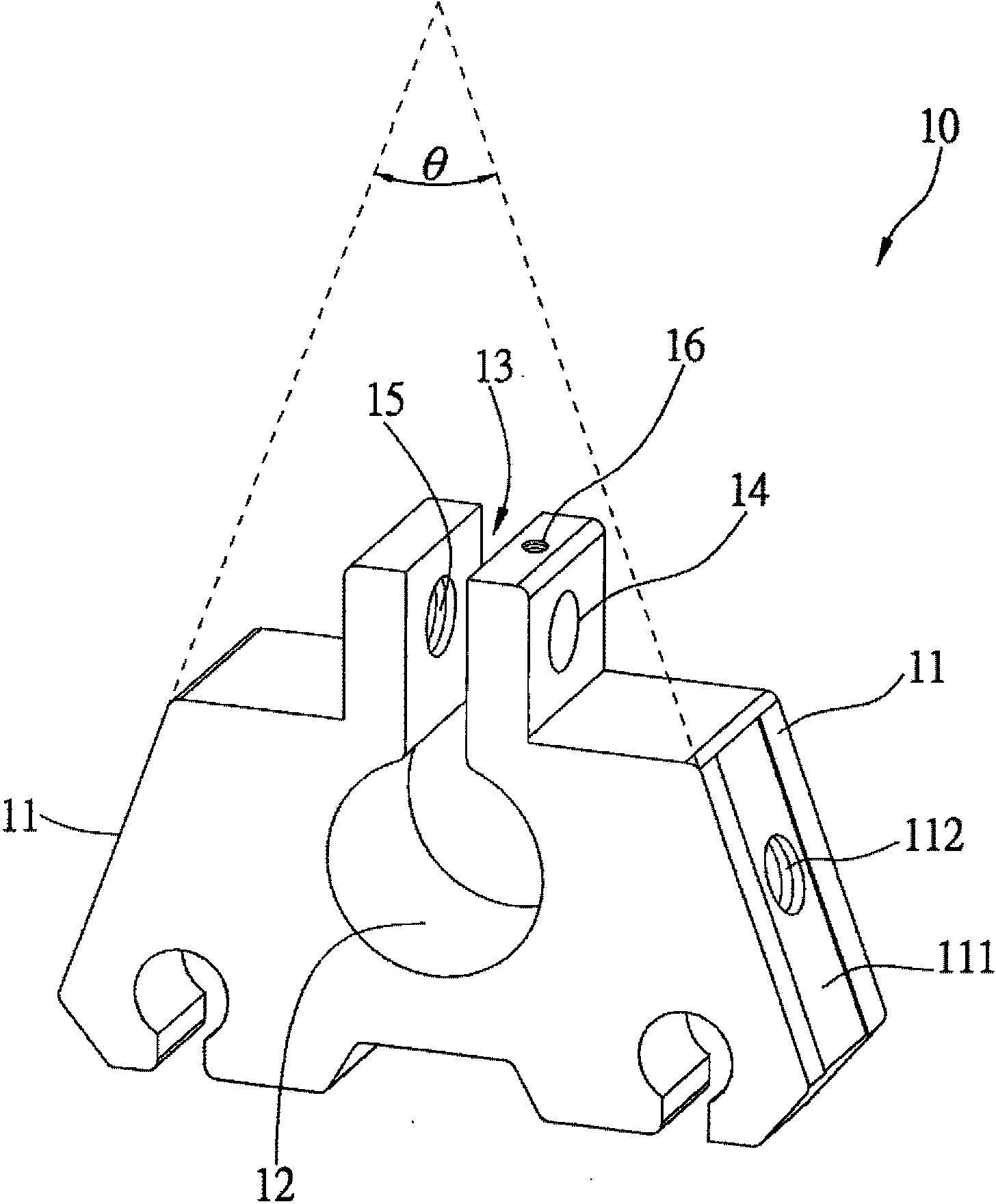
[0015] see image 3 , the joint base 10 is made of a conductor (such as copper) as a whole, and has two joint surfaces 11 , a shaft hole 12 , and a gap 13 connecting the shaft hole 12 and the outside of the joint base 10 . The two joint surfaces 11 are located on the opposite sides of the joint base 10, and the extension surfaces of the two joint surfaces 11 form an angle θ between 0° and 180° and extend downward and outward, wherein the angle θ It is better to be about 30 degrees as shown in this embodiment. In addition, a groove 111 is ...


PUM


Abstract

The invention relates to a collection ring carbon brush holder arranged between a fixing shaft and a collection ring. The collection ring carbon brush holder comprises a combination seat, two guide point supports and two carbon brushes, wherein the combination seat has two combination faces and a shaft hole, the two combination faces are arranged at front and back sides of the combination seat, the combination faces respectively dent to form a groove, the shaft hole is arranged between the two combination faces for penetration of a fixing shaft, each support has a first end and a second end, each first end is combined with one corresponding groove of the combination seat, the two carbon brushes are respectively combined with each second end and are used for contacting with the collection ring.

Description

technical field [0001] The invention relates to a carbon brush holder; in particular, it refers to a collector ring carbon brush holder. Background technique [0002] The basic structure of the motor includes an armature, a field magnet, a brush (carbon brush) and a collector ring. The rotation of the motor is provided by an external power supply to the carbon brush, and conduction is conducted through the contact between the carbon brush and the collector ring. circuit, the current passes through the armature, and generates a magnetic field around the armature, and the magnetic field interacts with the field magnet to make the motor rotate. [0003] The existing contact method between the carbon brush and the collector ring is to push the carbon brush up by the expansion force of a torsion spring, so that one end surface of the carbon brush contacts with the outer peripheral edge of the collector ring to conduct conduction, and then drives the armature to rotate. However, ...

Claims


Application Information

Patent Timeline
IPC IPC(8): H01R39/39
Inventor 游孟萩廖树城
Owner TAIWAN LONG HAWN ENTERPRISES
Learn More