Throwing and refloating device

A fishing device and main body technology, which is applied in the field of fishing devices, can solve problems such as the deflection of the main body of the connecting head fishing device, and achieve the effect of reducing the pulling resistance

Inactive Publication Date: 2016-12-14
CHINA PETROLEUM & CHEM CORP +1
View PDF7 Cites 2 Cited by
  • Summary
  • Abstract
  • Description
  • Claims
  • Application Information

AI Technical Summary

Problems solved by technology

[0005] The purpose of the present invention is to provide a fishing device to solve the problem in the prior art that the connecting head of the single-claw structure tends to deflect toward the direction of the fishing device main body

Method used


Image

  • Throwing and refloating device

Examples


Embodiment Construction

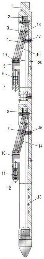
[0017] An example of a dropper is figure 1 As shown, it includes a thrower main body 1 extending in the up and down direction. The thrower main body 1 is respectively provided with a delivery claw mechanism and a salvage claw mechanism along the upper and lower sides, wherein the delivery claw mechanism includes a delivery outer claw 4 and a delivery inner claw mechanism. The claw 16, the upper end of the delivery outer claw 4 and the delivery inner claw 16 are respectively hinged with the fish thrower main body 1, and the hinge shafts are respectively hinge axis one 3 and hinge axis two 18, and the delivery outer claw 4 and the delivery inner claw 16 The lower end of the lower end is respectively hinged with the delivery joint 5, and the hinge axes are respectively hinge axis three 19 and hinge axis four 20, and hinge axis one 3, hinge axis two 18, hinge axis three 19 and hinge axis four 20 are respectively in four parallelograms. On the apex, the connecting line of the first...


PUM


Abstract

The invention provides a throwing and refloating device which comprises a main body of the throwing and refloating device, a connector and a claw mechanism connected between the main body of the throwing and refloating device and the connector, wherein the claw mechanism comprises an inner claw and an outer claw which are disposed inside and outside respectively; upper ends of the inner claw and the outer claw are in a hinged connection with the main body of the throwing and refloating device; lower ends of the inner claw and the outer claw are in a hinged connection with the connector; and two hinged points of the upper and lower ends of the inner claw and two hinged points of the upper and lower ends of the outer claw are located at four vertexes of a parallelogram. In comparison with a single-claw structure in the prior art, the device is characterized in that the double claws are disposed on the connector; the inner claw and the outer claw work together, and thus the connector is not deflected to the main body of the throwing and refloating device easily, so that a force bearing direction of a blocking device is consistent with a hole shift axis of a water distributor as much as possible, and lifting and pull resistance of the throwing and refloating device is reduced; and the four hinged points are located at the four vertexes of the parallelogram, and thus cooperative effects of the inner claw and the outer claw are ensured, so that joint effects brought by the inner claw and the outer claw to the connector can be ensured.

Description

technical field [0001] The invention relates to a thrower. Background technique [0002] At present, the eccentric distribution water injection process is one of the commonly used layered quantitative water injection processes in China. During normal water injection, the rubber tube of the packer is in an open state, and the oil layer is divided into several water injection layers. The plugs in each water injection layer are positioned on the expansion part of the upper part of the partial hole of the main body of the water distributor by means of cams. The upper and lower sides of the plug Set four packings to seal the partial hole liquid outlet. The injected water passes through the filter screen, enters the annular space of the oil pipe through the water nozzle, the liquid outlet groove of the sealing section, and the partial hole liquid outlet hole, and injects into the target layer. The layered water injection volume is controlled by the diameter of the water nozzle. W...

Claims


Application Information

Patent Timeline
Patent Type & Authority Applications(China)
IPC IPC(8): E21B31/12E21B31/06E21B23/00
CPCE21B31/12E21B23/00E21B31/06
Inventor 朱一斌朱劲羽陈金宝胡斌赵青李林森王超
Owner CHINA PETROLEUM & CHEM CORP
Why Eureka
Try Eureka